horz1

Thursday, December 1, 2016

Basic Tube amp from PRC (***Update#1***)

I came across the following mighty mouse on Amazon USA with many good reviews. It was being marketed under a different brand. However, US items are 110V and not suitable for local consumption unless you are willing to invest in a proper voltage conversion unit. For the cost involved, it was simply not worth it.

When I browsing on the China version of eBay (aka TaoBao), I came across the following amp - with specifications and looks matching the Amazon unit and available with a 220V transformer. Hence I bought a unit. It was likely to be the OEM version for local consumption.


Did have doubts of the "looks only" issue eg with different internals. 

A month odd later, the unit arrived. Weights about 9kg. Assembling and setting up was a breeze.

Initial power up and usage proved to be a shocking surprise! For the price, I was speechless by the delivery of the sound quality and workmanship of the unit. 

Apologies no pix of the internals - good thick quality blue PCB with audiophile components which included RIFA 429 poly caps!!!

With less than 20hr on the amp, it is proving to be extremely good value for money. The unit runs hot as it is a SET valve unit operating in Class-A mode with a modest 8W RMS per channel output - more than adequate grunt to drive my LS 3/5A+AB1.

Will provide more update next month once I have time to burn in the unit.


1Jan2017

After listening more to the PRC amp, I realised the reproduction of certain mid and HF tones were a little off. Checking the Amazon link for the non-OEM version, I discovered many reviews recommend replacing the Chinese military spec PRE tube with a Sovtek 6SL7. There were also reviewers recommending replacing the EL34 tubes provided but with just as many indicating to keep the EL34.

Hence I ordered the Sovtek 6SL7 to test the waters since it is not a hefty purchase. Once installed, the improvement was apparent after about 15-20mins. Initially there was a slight high pitched HF in the reproduction with the 6SL7. That slight HF pitch never return after the first 30mins. The reproduction of the voices was now more natural. Actually it was beginning to sound like my previous set-up with the Quad 33-303 acting as the amplifier, if you were listening to the PRC amp in passing aka not in-depth listening.

Am currently contemplating the next recommendation from the Amazon reviews - to change the EL34 ...

Tuesday, November 1, 2016

Analog-to-Digital Converter

I had an issue with the limited number of input sources for my older design units eg limited to single or only two sets of inputs.

Since my DAC is in-use most of the time, I decided to invest in a Analog-to-Digital (A2D) converter for consolidating the tuner output to the DAC. 

That was the easy part ... Had to search hard before purchasing the below as I did not realise how difficult it was to locate such a unit! Most of the market was geared towards Digital to Analogue (D2A) converters. Prices for the available A2D converters were quite shocking as well.

Analog to Digital converter from PRC
Bought the above from PRC since I was buying new batteries for my laptops at the time. The unit was delivered in a nice white box with magnetic latch. Inside the box was a manual in English (surprisingly), a short pair of normal RCA cables and a multi-voltage PSU unit. The unit has two outputs (RCA & TOSLINK) on one side with the LHS-RHS RCA analogue inputs and power connector on the opposite end.

Operation is simplistic as it operates in single direction only eg A2D not D2A. 

Initial testing with the RCA digital output was disappointing - low output volume and the audio quality was mediocre. Changing to TOSLINK, the difference was like night and day! Using a normal TOSLINK cable (about $6 from PRC) and the normal RCA analogue cable provided, my ES tuner sounds as good as the previous direct connection to the amplifier. 

Hence I am now able to use the DAC as a source consolidator for the older vintage amplifier units in my collection.

Saturday, October 1, 2016

DIY PROAC 2.5 Clone (Part- 3)

Continuation


Finally, the custom made clone cabinets arrived! It was delivered in a wooden crate with a label indicating the contents have a combined weight of 56kg!

Clone cabinets delivered (top of wooden crate removed)
Front of cabinets after un-boxing
Rear of cabinets after un-boxing

The physical dimensions were to specifications and the purchased bass port fits perfectly!

Testing how the bass port fits into the rear port opening. The crossover will be position opposite of the end of bass port, with most of the weight support by the bracing. Will use a velcro mechanism to hold the crossover to the internal wall

Since I requested for the bracing, had to literally force foam onto the bottom half of the cabinet. This is necessary to reduce unnecessary reverberations there. Had open-up a B&W 800 series before and that's what they use as well.

Putting foam into bottom half of the cabinet

Will be using MDM-2 in the top half of the cabinet.

MDM-2 for top half of cabinet
Forming top portion of MDM from package to fit top of cabinet, with cut along the edges
Fitting MDM inside top half of cabinet

Initial insertion of the ScanSpeak drivers onto the cabinets provided such a prefect fit I did not even have to deploy the screws for the first week of initial testing!

Initial fitting of drivers onto the cabinet

Ohm reading after insertion of speaker connectors and cabling of all internals

Close-up of one of the cabinets during initial usage

Initial usage was jaw dropping! Really sweet with bass to match ... no wonder the ProAc 2.5 is hardly available in the resale market.

It is a suprisingly power hungry speaker though. Will dig out my 200watt's power amplifiers once I have a chance to cleanup the room.

Shall update again once I have a chance to burn them in...

Saturday, September 24, 2016

Rhodium plated connectors

I had been pondering on a purchase of Rhodium plated connectors for a quite a while. Finally decided not to proceed.

A brief intro to Rhodium for those not familiar. Rhodium is a rare earth element in the same group as platinum, gold, silver, etc. Quote from Wikipedia - "Being a noble metal, pure rhodium is inert. However, chemical complexes of rhodium can be reactive." 

Rhodium plated items are not cheap. They are normally available as high end automobile spark plugs as well as high end hifi connectors.


Decided not to purchase any Rhodium plated connectors after someone on a hifi forum who was touting the benefits of using an high end contact cleaning fluid on their own Cardas Rhodium speaker connectors. He show a pix of the contaminants after using the high end contact cleaning fluid on a cotton bud afterwards, as well as reporting audioble reproduction improvement.

One has to ask - is the Rhodium plating of the Cardas Rhodium connector pure??? 

Based on the chemical properties of the element Rhodium, it should be inert. In theory, when he cleaned the Cardas Rhodium connectors, there should be no noticable residue to the naked eye - not the proportionally largish dark patch on the cotton bud, as shown ... unless it was not pure Rhodium but a chemical complex based on Rhodium.

Hence my personal logic is why pay extra for this Rhodium plating when one still has to clean the connector vs a normal gold plated version ... unless you have plenty of extra cash to spare

Thursday, September 1, 2016

DIY PROAC 2.5 Clone (Part-2)

Updates

The cabinets have been completed and the provider have requested for additional curing time before putting the finishing touches. Looks like I can only complete the DIY after another month or so. The pix the provider sent over did look ok but were very low resolution.

Will be purchasing the specified drivers from overseas, as the local agent pricing was not that convincing (prices are before GST). In addition, delivery costs are extra from the agent.  In the past, I have bought quite a number of drivers from overseas without issues - hence no brainer for myself. It's my choice and am comfortable with it - hey I have even Fedex a 29kg power amplifier from overseas before!

In the meantime, most of the PRC Ebay items arrived about 2-3 weeks after payment - as per below.

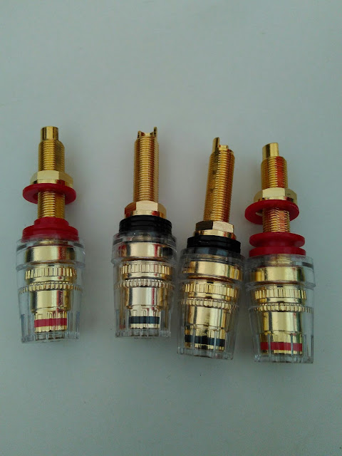
Speaker driver terminal connectors 
Speaker terminals with long lugs


Managed to locate a ready made bass port with the required specs - would have preferred a all plastic component though.
Correct spec ready made bass port for the cabinet


The following cutout was made in preparation for drilling the holes to place the speaker lugs with provision for a bi-wire layout (since I was at it). Will position the bottom of the cutout just above the bass port opening of the cabinet. Then will drill the designated 1st set only.
Cardboard skeleton for drilling speaker terminator lugs

Bought these from a local hardware store. S&P within PRC was not viable.
For cable termination from crossover to speaker lugs


The following pix shows the clone crossover schematic at the top, and, the PCB circuit diagram for the crossover board purchased at the bottom. You can see my scribbles over the PCB schematic.
Reference circuit diagram at top with the modifications for the PCB layout

The main reason to buy the crossover PCB was to simplify the crossover component layout and permit a compact PCB vs a DIY crossover board. In addition, the compact PCB can be positioned thru the woofer driver port and will fit neatly between the woofer and the bracing within the enclosure, in a vertical position with the back of the PCB against the wall (using the internal bracing to hold the weight of the crossover). If you refer to Part-1 for the enclosure specs, you will then understand why.

I decided to not separate the tweeter and woofer access points as I do not see any real advantage doing so. Anyway, it is relatively simple to convert the PCB connections to support a bi-wire configuration (separate and hook-up 3 GND connections on the tweeter circuitry), since the connectivity on the PCB has been separated into INPUT and GND for inputs with HF OUT, LF OUT and GND for outputs. Another reason for choosing this particular PCB.
Completed crossover


For the curious, the inductors are constructed from 1.5mm copper and hence weights quite a bit. I did find it necessary to cut the original straps on the inductors, to reposition the termination point for better connectivity to the PCB. Had to re-drill the PCB holes for the inductors as the original on the PCB were just too small.  The green caps are 1uF Russian PIO (Paper-In-Oil) capacitors. The black caps are ERSE Audio. The PIO(s) were combined in-parallel to create the custom values as per specified on the clone schematics. The PIO in the middle of the PCB was mounted on a daughter DIY board (space restrictions). The ceramic resistors were purchased from Malaysia as they cost about SGD$2 (each!!) locally  and are much cheaper in Malaysia (roughly SGD1->MYR2.98). A friend help acquire them on a family trip.


Internal cables will be as per my DIY LS 3/5A. Had to re-drill the PCB to accommodate these cables as well.

Am awaiting for delivery of black hex screws for securing the drivers to the cabinet.

Monday, August 1, 2016

DIY Quad PRE/POWER DIN-RCA interface

While awaiting parts for the Proac clone to arrive, I finally had the need to make the following for myself (after making a few for clients).

It's a simple interface converter to enable old Quad models to be connected to other equipment. Pin-outs are at http://myoldvintagehifi.blogspot.sg/2012/02/bi-amping-quad-303.html

Plastic case from EBay
4-pin DIN for Quad pre/power amp connectivity to RCA
RCA from Ebay
Decided to try using a solid copper core for transporting the LHS and RHS signals, as the previous units were completed using normal cables. Earth connectivity remain unchanged.
Solid core copper cable used for connectivity
Been using it everyday for the past week ... so far, so good 

Saturday, July 2, 2016

DIY - PROAC 2.5 Clone (Part-1, ***Update***)

I decided to initiate a DIY clone of the infamous PROAC 2.5 as have given up trying to purchase one in the used market after searching for years. A hifi dealer I frequently dealt with, informed he has never came across one for sale yet.

Searching the internet for information, the most promising clone seem to be the one at http://www.justblair.co.uk/blog/137-diy-proac-response-25.html as there were positive feedback from previous owners of the actual unit who long for another chance of ownership, and, made the clone using the information from the link as reference.

From past experience, my main hurdle was the enclosure. I am not capable nor have the equipment/facilities necessary to fabricate them. Fabricating them locally would cost "an arm and a leg".

My previous EBay contact (REF: DIY LS 3/5A) quoted an expensive cost for the cabinets only (with S&P)!!!

Fortunately during my exploration of the Chinese version of EBay, I stumble across a vendor who fabricates speaker enclosures. Hence I provided the above link for reference and the vendor says NO PROBLEMO. Total cost would be much lower. Naturally I placed the order and now praying for the best ...

In the meantime, I am going thru the parts list and buying most of the necessary parts from the Chinese EBay site. After all why pay a 3rd party who would purchase from China and resell to you for a profit, right?

We have to face the facts, most items are nowadays manufactured in China - there is really no choice.

I will only be buying the capacitors and actual drivers from non-China sources.

Hope to update next month, once I receive the items.


3 October, 2022


Decided to update this post after I received a 404  when clicked the justblair link, in-case the link will not be reinstated.

I scanned the web and managed to locate the cabinet diagram I previously used for the project. I did not include it in the original post as we could refer to the justblair site previously.

In hind-sight, should have taken the opportunity to add or include a plint base for the DIY.


NOTE:

If you are considering undertaking such a project, you must remember that the original did not use expensive or the best capacitors or resistors, yet the resultant speaker created a loyal cult following.

Hence if you contruct the crossover with above average quality components, the DIY should deliver results you can be proud of!

Since better than average quality 3.4uF and 7uF poly axial poly capacitors are hard to come by, you could create alternatives by connecting your preferred replacements in parallel (REF: connecting capacitor in series and parallel).

In addition, I had the opportunity to peek inside a B&W 800-series speaker few years ago. The internal space was fully loaded with only low density foam, no damping mat etc. Hence there is really no requirement for special rubber damping mats or tar based sheets etc when simple low density foam and standard "off-the-shelf"  materials such as MDM will suffice.


Monday, June 6, 2016

DIY - Experimental Open Baffle speakers (Part3)

Apologies as I have been busy with my (discounted) shopping spree on China's version  of eBay ... kept feeling I had not done something recently!!! Finally remembered what it was...

After much searching, found what seem to be the proper replacement for the original crossover board on the Pioneer S-D77 (now DIY Open Baffle) speakers - see pix(s) below.

Original crossover from the Pioneer S-D77
Replacement crossover from China

The replacement was a ready made 2nd order 3-way crossover with 2dB boost on the HF.

How does it sound vs the original crossover?

Initially the PRC crossover sounded as if it someone had place a thick floor mat over it - even with the 2dB boost! After a couple of days, it began to remove the "thick floor mat" - details was then neither here or there, but reproduction was beginning to open-up. After a few more days, it sounded close to the original crossover. About a week later, bass details started leaping out.

A few of my visitors were pleasently surprise by the quality of audio reproduction from the DIY Open Baffle, when driven by my Audiolab 8000A.

Hmmm ... how much did I pay for my pair of production speakers from the shops??? Bloody hxxx ...

Sunday, May 1, 2016

Internet streaming using PC via USB DAC

Finally had the time to hooking up my DIY TDA1541 DAC to the PC via USB to the hifi set.

The PC is an older laptop which I have since redeployed for live streaming for songs (Spotify, etc) and sports event(s), etc. Since the USB DAC was Plug&Play compatible, setup was a breeze after making sure all the necessary cables are in-place, and, flicking the toggle switch on the back of the DAC chassis.

Initial setup for testing

As  this is the 1st time using the DAC components, initial reproduction was a tad bassy when compared to the output from my Sony ES tuner, for the same FM station. Otherwise the details were all present. Will update once it has been run-in.
The DIY USB DAC with TDA1541
Connections on the rear

Friday, April 1, 2016

Philips CD-880

The Philips CD-880 was my 1st proper CD player. I actually had my heart set on the Philips CD-650 but was informed it was no longer in production, and, the CD-880 was it's successor when I had save enough to buy one in 1989. Paid $1250 for the CD-880.


Philips CD-880 pix from the net

Don't think I need to go over the specifications etc for the unit as it is quite a well known unit and there are many sources of such information on the net. 

What I will do is provide information regarding what's not well known about the CD-880. I owned one for 13 years before deciding to sell it.

The unit was mainly plastic and thus quite light. If memory serves, was about 6kg. The laser does not read from the old blue dye CD-R which were available at the time.  The tray mechanism was not as solid as the Sony ES series but did an adequately job; had a built-in adapter for the smaller single version of CD.

The remote was well design and pleasant to use.

Variable output from the CD-880 had too much HF for my taste. At that time, I tested the results by connecting the CD-880 directly to a Carver power amp with a pair of Celestion SL-6s. Fixed output was much better but still a little lean on the bass. Extremely fluid and rich mids thanks to the TDA1541A.

Another plus was the shock absorption capability of the attached feet to the base of the unit - the CD-880 would play non-disruptively unless you gave it a hard knock squarely on it's chassis!

Personally I think the display presentation of the CD-880 was the best of the lot ... looks cool, even after more than two decades!!!

Do I have any regrets selling my CD-880? No, as I still prefer the sonic signature of it's predecessor.

Tuesday, March 1, 2016

DIY - Experimental Open Baffle speakers (Part 2)

(continuation from Part 1)

After some plastic surgery, the ugly duckling was transformed to the below. Woofers were salvaged from the original Pioneer S-D77. Replacement midrange are AIWA and tweeters Celestion.

The resultant open baffle
Initial layout after hooking up the misc components

Frontal view
How does it sound?

In short - blew my socks off (... can't find them)!!! I NEVER expected such promising results. The resultant open baffle (aka OB) sounds extremely open and natural. Using the setup in the living room, I could hear additional details from my favourite CD(s) I never realised were in the recordings ... till now! Even so, bass reproduction seem to change drastically between CD(s) which could be due to the resulting impedence or matching of the make to do components. Nevertheless this seem to be the common sore point for the many OB(s) on the net.

Was originally planning to dispose of these cabinets after some mucking around ... I now intend to order some decent components for further exploration. Much followup would be necessary before I can finalise the replacement crossover for the OB ... guess will require a Part-3 for the OB in the near future.

In the meantime, I started performing "trial and error" tests using the many components in my collection. Changing the DAC in the above setup produces large differences in the quality of reproduction.

Monday, February 1, 2016

DIY - Experimental Open Baffle speakers (Part 1)

Since I now have a crippled pair of Pioneer S-D77 speakers at my disposal, I went thru my inventory of spare drivers to determine if any could be attached to the cabinets to get them going again.

Unfortunately none of the available drivers could not be mounted onto the cabinets as per original as the baffle cutouts were (again) just too small.

As the cabinets were glued together (no screws), it is very troublesome to attempt fitting the available parts from internally. Fitting them externally onto the cabinets would create a Frankenstein ... the boss will not approve!

I was considering salvaging the usable parts before disposing of the cabinets. It was then the idea hit me - why not convert them into an experimental Open Baffle speaker?? Always wondered how a pair of open baffle speakers would sound in my living room after hearing a pair of Gradient Helsinki at a local AV show couple years ago. LOVELY ... until they told me how much a pair costs!!!

Anyway... back to reality.

Planned steps of action are:-

1. Investigate available DIY open baffle (OB) designs on the net
    - Most the OB implementations on the net seem to be ground up implementations eg from scratch
    - These implementations have several common characteristics
      - baffle to house the drivers
      - some with, others without a base for bracing the baffle
      - wide unrestricted rear to maximise sound dispersion
      - OB kits seem to cost an arm and leg, even before shipping
      - minimal information on the crossovers deployed on most projects
        - need to test before we will know if a different crossover will be required for an OB?

2. Draw the desired outlines onto the existing cabinets
    - Since I have a jigsaw and sander handy, decided on a simple straight line cut-out of cabinets
    - Will retain only the baffle and the speaker connectors on the base

Cutting outlines for the cabinets on masking tape. LHS cabinet shows the rear, RHS cabinet shows the side
3. Remove all drivers and misc components from the internals. Ensure the misc cabling out of harm's way when jigsaw bites

Stock crossover on cabinet before the jigsaw bites
4. Jigsaw away the undesired portions of the cabinets*
    - Extract the stock crossover afterwards since originally fastened to the side of the cabinet
      - Tried unsuccessfully to remove the crossover before jigsawing
        - The enclosed cabinet makes for difficult DIY-ing

5. Sand away any sharp edges after the jigsaw is done*

*For those not living in Singapore, I need to explain the reason for delaying the metamorphosis. As I am one of the many Joe's residing in a government flat (just about 90% of the population), I can only create the mess in the external areas (with the all the accompanying din) during limited hours of the day and must cleanup afterwards. Would be an effort to do so after jigsawing and sanding the cabinets. Since the authorities do perform a wash-up of these external areas on a certain day of month, I should take advantage of this scheduled activity! Heh heh heh ....


6. Install the available pairs of tweeter and midrange units (same Ohms) onto the inside of the baffle
7. Reuse the original woofers
8. Reconnect all components to the correct wiring and polarity to the original crossover
9. Test the resultant OB


Friday, January 1, 2016

DIY - possible simple solution to deteriorating sound from a Quad 33 channel

Over the years I discovered it is necessary to clean the copper contacts on the add-on boards on some vintage hifi components every so often. This is especially true for my Quad 33 since I am now residing in the tropics. The Leaks seem to be trouble free at the moment ... touch wood

Some of the symptoms I have experience are the following, and, these occurred even after I use contact cleaner on the potentiometers and push-buttons:-

- one channel cutout and remain silent after some initial low level crackling upon powerup
- crackling sound on one channel which seem to get louder and occur more often as time goes by
- volume on one channel which seem to get lower and lower over time

One option is to use contact cleaners. Spray some onto a cotton-type cloth of sorts and use it to rub against the contacts. Unfortunately I find the results does not last long. You would need to repeat the procedure about every 3-4weeks due to the effects of the hot and humid climate.

After some experimentation I now use a different procedure. A good quality pencil eraser is recommended. Give these copper contacts a good rubbing with the eraser. I normally hold the board in one hand and ensure only the contact end of the board are say 1cm are inside the edge of a table. Then use the other hand to deploy the eraser. This will ensure minimising the possibility of damaging the board, Once completed, please ensure no eraser leftovers are on the contacts before reinsertion into the unit,

My Quad 33 boards seem to require such maintenance every  few months. One of my clients with a Quad 33 has the same issue and was quite surprise by the effectiveness of such a simple solution.

So save yourself a costly trip to the shop by giving the above a go before that.