horz1

Saturday, September 24, 2016

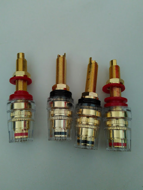
Rhodium plated connectors

I had been pondering on a purchase of Rhodium plated connectors for a quite a while. Finally decided not to proceed.

A brief intro to Rhodium for those not familiar. Rhodium is a rare earth element in the same group as platinum, gold, silver, etc. Quote from Wikipedia - "Being a noble metal, pure rhodium is inert. However, chemical complexes of rhodium can be reactive." 

Rhodium plated items are not cheap. They are normally available as high end automobile spark plugs as well as high end hifi connectors.


Decided not to purchase any Rhodium plated connectors after someone on a hifi forum who was touting the benefits of using an high end contact cleaning fluid on their own Cardas Rhodium speaker connectors. He show a pix of the contaminants after using the high end contact cleaning fluid on a cotton bud afterwards, as well as reporting audioble reproduction improvement.

One has to ask - is the Rhodium plating of the Cardas Rhodium connector pure??? 

Based on the chemical properties of the element Rhodium, it should be inert. In theory, when he cleaned the Cardas Rhodium connectors, there should be no noticable residue to the naked eye - not the proportionally largish dark patch on the cotton bud, as shown ... unless it was not pure Rhodium but a chemical complex based on Rhodium.

Hence my personal logic is why pay extra for this Rhodium plating when one still has to clean the connector vs a normal gold plated version ... unless you have plenty of extra cash to spare

Thursday, September 1, 2016

DIY PROAC 2.5 Clone (Part-2)

Updates

The cabinets have been completed and the provider have requested for additional curing time before putting the finishing touches. Looks like I can only complete the DIY after another month or so. The pix the provider sent over did look ok but were very low resolution.

Will be purchasing the specified drivers from overseas, as the local agent pricing was not that convincing (prices are before GST). In addition, delivery costs are extra from the agent.  In the past, I have bought quite a number of drivers from overseas without issues - hence no brainer for myself. It's my choice and am comfortable with it - hey I have even Fedex a 29kg power amplifier from overseas before!

In the meantime, most of the PRC Ebay items arrived about 2-3 weeks after payment - as per below.

Speaker driver terminal connectors 
Speaker terminals with long lugs


Managed to locate a ready made bass port with the required specs - would have preferred a all plastic component though.
Correct spec ready made bass port for the cabinet


The following cutout was made in preparation for drilling the holes to place the speaker lugs with provision for a bi-wire layout (since I was at it). Will position the bottom of the cutout just above the bass port opening of the cabinet. Then will drill the designated 1st set only.
Cardboard skeleton for drilling speaker terminator lugs

Bought these from a local hardware store. S&P within PRC was not viable.
For cable termination from crossover to speaker lugs


The following pix shows the clone crossover schematic at the top, and, the PCB circuit diagram for the crossover board purchased at the bottom. You can see my scribbles over the PCB schematic.
Reference circuit diagram at top with the modifications for the PCB layout

The main reason to buy the crossover PCB was to simplify the crossover component layout and permit a compact PCB vs a DIY crossover board. In addition, the compact PCB can be positioned thru the woofer driver port and will fit neatly between the woofer and the bracing within the enclosure, in a vertical position with the back of the PCB against the wall (using the internal bracing to hold the weight of the crossover). If you refer to Part-1 for the enclosure specs, you will then understand why.

I decided to not separate the tweeter and woofer access points as I do not see any real advantage doing so. Anyway, it is relatively simple to convert the PCB connections to support a bi-wire configuration (separate and hook-up 3 GND connections on the tweeter circuitry), since the connectivity on the PCB has been separated into INPUT and GND for inputs with HF OUT, LF OUT and GND for outputs. Another reason for choosing this particular PCB.
Completed crossover


For the curious, the inductors are constructed from 1.5mm copper and hence weights quite a bit. I did find it necessary to cut the original straps on the inductors, to reposition the termination point for better connectivity to the PCB. Had to re-drill the PCB holes for the inductors as the original on the PCB were just too small.  The green caps are 1uF Russian PIO (Paper-In-Oil) capacitors. The black caps are ERSE Audio. The PIO(s) were combined in-parallel to create the custom values as per specified on the clone schematics. The PIO in the middle of the PCB was mounted on a daughter DIY board (space restrictions). The ceramic resistors were purchased from Malaysia as they cost about SGD$2 (each!!) locally  and are much cheaper in Malaysia (roughly SGD1->MYR2.98). A friend help acquire them on a family trip.


Internal cables will be as per my DIY LS 3/5A. Had to re-drill the PCB to accommodate these cables as well.

Am awaiting for delivery of black hex screws for securing the drivers to the cabinet.