horz1

Friday, August 1, 2025

DIY PCB for dual mount TDA1541 (***Part-2***)

Finally completed the soldering for the dual TDA1541 PCB which required some planning as the solder holes for the 0.1uF capacitors near the center of the PCB, over-lap the interface pins for the destination  TDA1541 holder below! 

Top view

Bottom view

Took awhile before I could complete the soldering as had to searched for the required capacitors which had been misplaced - knew I had some spares lying around but these were not where I thought they were ... that's age catching on you! 

Blue capacitors are EPCOS 0.1uF 100V and red are WIMA 470pF 1000V - just using the surplus instead of buying more suitable replacements. It was necessary to bend the capacitor leads before they could fit into the solder holes on the PCB.

For those attempting to complete some soldering with a IC DIP holder, do take care not to damage the fragile pins on it, as I had done. I re-deployed the damaged DIP IC holder to protect the under-side pins of the above PCB.

Be careful not to damage the pins on DIP IC holders, as I had done

More pins on the under-side of the PCB

While searching for the mis-placed capacitors, I used the multi-meter continuity tester on the connections for LHS/RHS data-in/out of the two TDA1541 on the PCB and these connect directly to the same output pin number(s) at the external mounting point on the under-side of the PCB. Thus the various capacitors on the PCB are only to enable the DAC IC to function as per specification sheet.

Need to dig out a old CDP and/or change to the lower height caps on the DIY TDA1541A DAC before any listening tests can be perform ... for the future

Tuesday, July 1, 2025

DIY - Solving Quad 33 one channel no sound

After fixing the "broken" balance control on Quad 33 #2, I then discovered there were a few things not right on this Quad 33. 

Most apparent issue was 😒only RHS had audio.

The rectification adventure was "interesting". Here's how it unfolded:-

  1. Powering-on the Quad 33 #2 now came with a "loud thud". Could see the suppressing RIFA on the volume control. However on closer inspection, I then saw the physical damage inside the insulating plastic. As I did not have a exact replacement (RIFA 0.047uF X2) on hand, I used a spare 0.1uF X2 275V ... does the job.
    How to connect the suppressive capacitor
    Bad RIFA X2

    Alternative X2 capacitor


  2. Next was to perform the most basic test - swap the LHS with the RHS amplifier boards, no effect. "Borrowed" the amplifier boards from Quad 33 #1 (aka #1 from here thereafter), same result. Only RHS had audio.
  3. Proceeded to swap the other Quad 33 boards from #1, again no difference.
  4. This would imply an issue on either the motherboard PCB, the connections, and/or switches on the unit chassis.
  5. Visually checking the unit reveals no obvious issues.
  6. Searching the various online forums reveal many such issues, caused by various part failure(s) due to age of the components.
  7. Since I do not have an oscilloscope, I will have to use my Digital Multi Meter (aka DMM) and test for bad components one at a time (without removal from the PCB - yea, was lazy and hoping to strike gold!). They all passed😕
  8. Not satisfied I reference the Quad 33 schematics and started to unsolder capacitors from the motherboard for testing. The moment I unsoldered C3, the capacitor just drop out as one of it's leads dislocated from the main capacitor body. Since I did not have a spare 0.033uF axial capacitor, I substituted a similar spacing size 0.022uF to test if that is the source of the problem. 😒still no audio from LHS but did note this time I could hear a soft "pof" from the LHS during power-on. Rest of the LHS capacitors on the motherboard passed.
    Broken 0.033uF capacitors which fell out upon desoldering

  9. Stumped, I decided to try swapping the amplifier boards again. 😮There was now audio on the LHS but not RHS😕??? Hence I borrowed the amplifiers boards from #1 again - confirmed now there is audio on LHS but not RHS!
  10. Thus now repeating Step-7 for RHS circuit on the motherboard, to discover that C10 failed in the same way - capacitor lead broke away after de-soldering and fell from motherboard. Used another 0.022uF as temporary substitute and there was now audio from both channels when using the amplifier boards last deployed (from #1)😁
    C3 and C10 on the Quad 33 motherboard schematic

    C3 & C10  high-lighted on the Quad 33 motherboard
    C3&4&9&10 replaced on the Quad 33 motherboard


  11. Will replace C3&4 on the LHS and C9&10 on the RHS channels, to ensure "sonic matching" since there is a potentiometer in between these capacitors (on both channels).
  12. Next I returned #1 boards and reseat the original amplifier boards (from #2) back into the Quad 33 ... 😕again no sound from RHS??? However this time the audio moved when I swapped  the LHS and RHS amplifier boards.
  13. Therefore, there is a bad component(s) on the original RHS amplifier board.  Resumed testing components one-by-one using the DMM and transistor tester. Finally ... R406 was the bad component (270Kohm 1/4watt).
    Bad R406 270Kohm resistor on amplifier board


  14. Once R406 was replaced, both audio channels were audioable again. Had to adjust the balance slightly as the reproduction was just slightly off centered. Most likely cause is the use of different brands/make/wattage resistors on both amplifier boards - "re-alignment" task for another day...


Finally realised why Quad 33 #1 did not experience any issue of loss of audio on 1-channel - I had replaced all the axial capacitors on that motherboard long time ago as I wanted a unit to compare the reproduction difference when using original vs modern capacitors!!!


Sunday, June 1, 2025

FYI Quad 303 owners - Check the condition of your driver board capacitor(s) (***Updated***)

 Hi everyone,

Please do check the condition of the electrolytic caps on the Quad 303 driver boards every once in a blue moon, especially the condition of C101.

C101 as per high-lighted, on the Quad 303 driver board pix from the service manual

I chance upon mine while investigating why only one channel was audible when using the Quad 33 from last month (since discovered had several problems).


Quad 303 #1

Please refer to the pix below.

C101 on each driver board - note the darken area towards bottom half of each capacitor


Even though the power amplifier performed flawlessly, the visually impacted C101 could be sign of a latent issue at large as these FC(s) were purchased from Element-14.

I troll the DIY forums for information regarding any similar observations. While I did not manage to locate any, I did note there were many reported issues originating from the PSU board. Since C101 on both boards were impacted, this had to be the common source of the issue!

Thus I obtained an updated Quad 303 refresh PDF from DaDa Electronics and followed the bias-ing procedure. 

Immediately discovered the issue - PSU was pumping out 74V and adjusting trimmer RV200 had no effect at all!!!

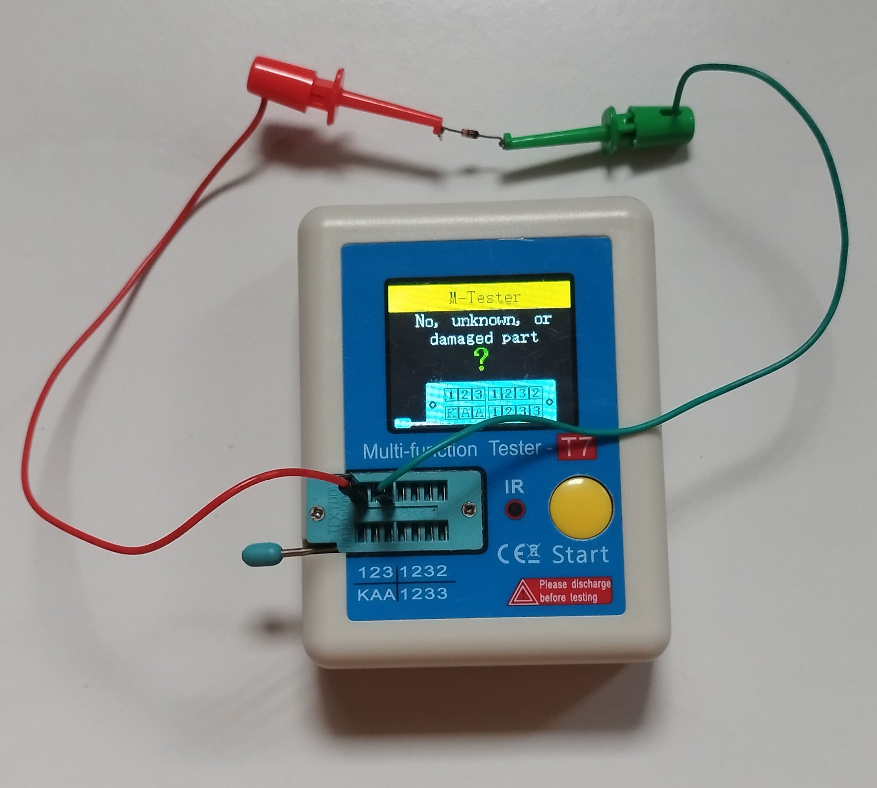
Testing TR201 using a el-cheapo tester from AliExpress shows that it was faulty and behaved as if it was 2 diode(s) which output to the 3rd pin - see following pix.

Result when testing TR201 on the transistor tester


Ordered a replacement BC441 as I already have the appropriate heatsink. While awaiting for the BC441 to arrive, I changed RV101 from 2K2 to 22K on both driver boards (since the S/N of the unit was well below 11000) as per recommend by the PDF.

After repairs


Since I have a few spare 470uF 35V lying around, will use them 1st to "test the waters" till I can purchase proper audio EC capacitors for C101.

Upon installing BC441 as TR201, the PSU was initially outputting 60V. I then followed the bias-ing procedure and obtained a result close to the recommendations.


Quad 303 #2


Checking #2, found the same C101 issues as well. 

The PSU on this unit was outputting 78V+!! Adjusting RV200 could only bring down the voltage by decimal points! Hence power-ed down the unit immediately and re-position the trimmer to mid-point.

The cause for unit #2 was not TR201, as checking the transistor via the el-cheapo AliExpress tester indicates it's working fine. 

Proceeded to test the various components on the PSU board via a Digital Multi-meter (aka DMM) which then reveal diode MR200 was in open status. 

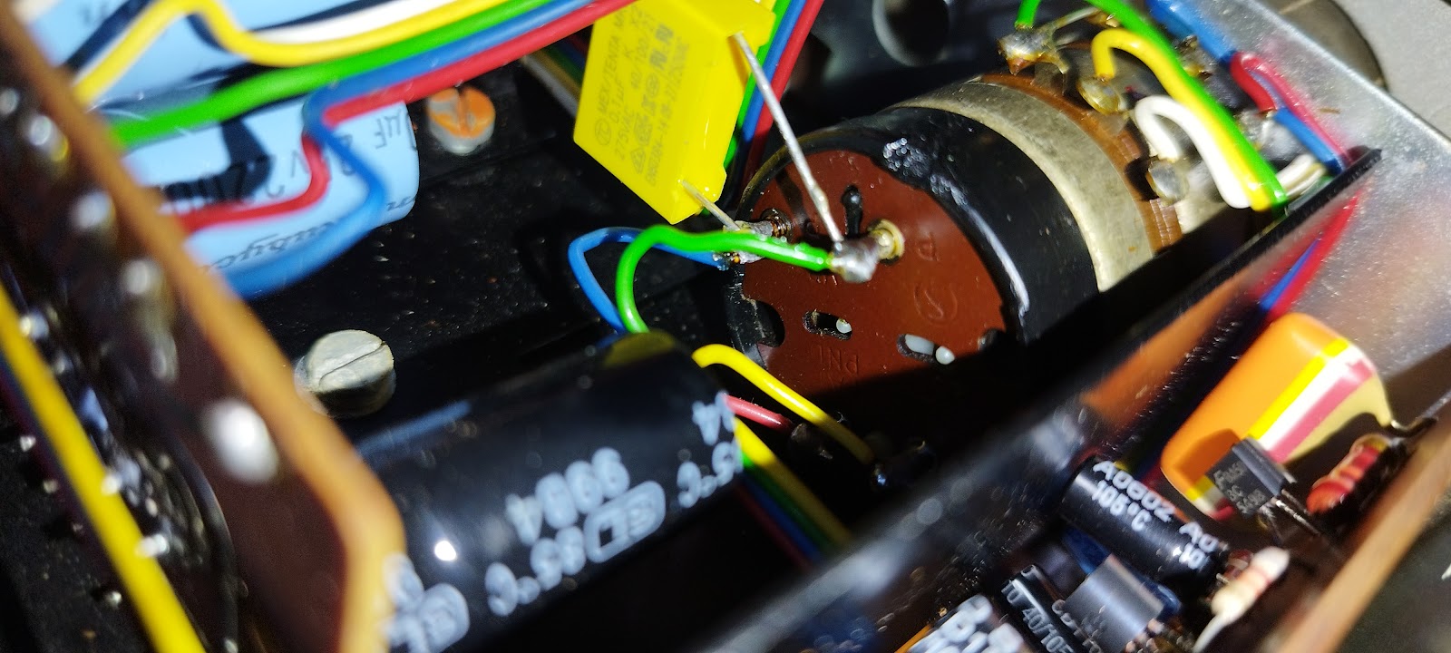
Tester confirm bad diode detected during DMM inspection of the PCB


Replaced MR200 with a 1N4004 diode, as per suggested by the PDF.

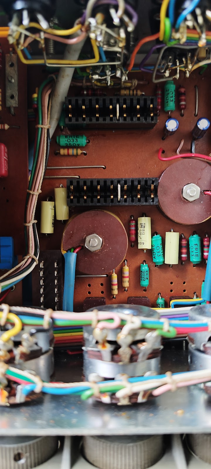
The diode, MR200 on the Quad 303 PSU


Took the opportunity to change RV101 from 2K2 to 22K on both driver boards since the S/N of the unit was well below 11000. And used the spare 470uF 35V until I can purchase proper audio EC capacitors for C101.

Upon power up, voltage was 76V+ but could be reduced via adjusting trimmer RV200. Again, followed the bias-ing procedure and obtained a result close to the recommendations.


Quad 303 #3 (Update 27Jul2025)


Finally had the urge to take a look into Quad #3. Here's how it went ...

  1. Upon power-up, there was a loud thud sound on the RHS channel, followed by a consistently mid-volume "burrr" with no audio during playback. LHS was performing as per expected.
  2. Next, the black RHS banana jack receiver on the Quad broke😒as I was swapping the speaker connection for further testing.
  3. Noted the entire heatsink was becoming quite warm as well.
  4. Since I could not do much more, I desolder RV101 from both boards, took their resistance reading, set the replacement 22K to the previous reading(s) for the respective boards before resoldering them.
  5. Ordered replacement banana plug receivers and was received the day a few days ago.
    Round version new


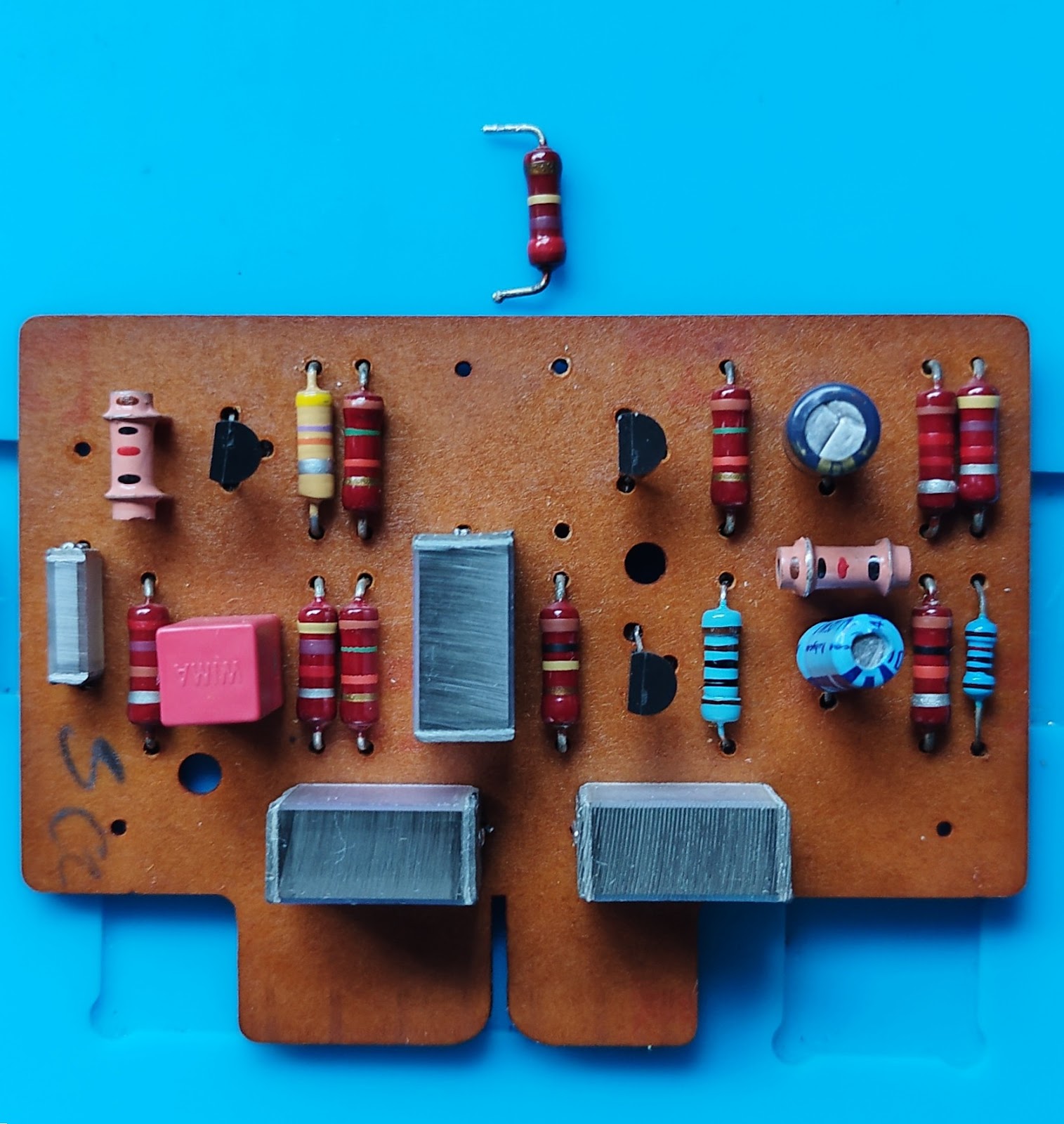
  6. As the impacted RHS board was an older Issue 5, I could not locate a specific schematic for it. Had resorted to "1-for-1" part replacement for transistors. Unfortunately 1 could not read the markings of one transistor, closest to the driver input drill holes on the PCB - turns out to be the new BC560 - using process of elimination via presence of the other transistors.


    The transistors with heatsinks need to be replaced on the Issue 5 board - shown with transistors replaced on the sides


  7. Removed the 2 transistors with heatsink before power on. Upon power on, no unexpected sounds eg no loud thud, no burr-ing & heatsink not heating up - indicting the bur-ring sound was not from an earthing issue. Hence power down the unit and swap with new BC441&461 with heatsinks.
  8. Power up this time no loud thud and no bur-ring, but also no audio.
  9. Power off and started to de-solder the remaining original transistor(s) for verification on the transistor tester. All passed the tester??? 😟
  10. Using the DMM to test the resistor(s) and diode(s) indicate all these parts are ok.
  11. No choice then, kept repeating to swap out the remaining transistors one at a time, then power on to test repeatly. Luckily I bought a few extras since had to look into possible issues for few Quad 303(s). In the end, had to replaced each and every transistor on the RHS board.
  12. Eureka!!! Everything works now with the resultant imaging at roughly same spot as the previous(s) Quad😆. Bonus was heatsink now not warm at all😁
  13. Will take the win & perform a bit of listening tests before performing the bias-ing a little later


Thursday, May 8, 2025

DIY Hack for broken Quad 33 Balance control "U"hook

Took my 2nd Quad 33 (refreshed Electrolytic Capacitors only) from storage only to discover the balance control does not work. 

After doing due diligence inspection of the Quad 33 boards and spraying contact cleaner everywhere, saw the broken "U" shape hook at the end of the balance control slider. I may have tried to move the slider too hard as it was pretty stiff, breaking that fragile piece of old plastic in the process.

From the internet, as there is no pix of the slider in the service manual


Tried to purchase a replacement but could not locate any spares for sale anywhere.

Then I had an idea - why not use a strong string of sorts eg fishing line, badminton racket string, or alike - tie a knotted loop around the protruding metal piece (maybe adjust so closer to edge of the slider) and tie another knotted loop around the remaining plastic piece eg resulting in a figure-8 shape. 

That did the job - see the pix(s) below. 

1st knotted loop, around the protruding metal piece

2nd knotted loop around the remaining plastic piece

Will perform a proper replacement ... someday😏


Note: Spraying contact cleaner into the balance potentiometer did restore smooth operation

Wednesday, April 9, 2025

Quad 5-pin DIN connector pinout

From internet


Recently dug-out my Quad 33 for a run, only to discover one of the 5-pin connectors did not work properly - only RHS had audio.

Had been a while since using the Quad 33 and was at a loss regarding the pinouts😓.

Thankfully nowadays there is the internet and after some searching found the above - had forgotten the information was at the back of the unit itself😳

For those in the same boat ...😁