horz1

Tuesday, July 1, 2025

DIY - Solving Quad 33 one channel no sound

After fixing the "broken" balance control on Quad 33 #2, I then discovered there were a few things not right on this Quad 33. 

Most apparent issue was 😒only RHS had audio.

The rectification adventure was "interesting". Here's how it unfolded:-

  1. Powering-on the Quad 33 #2 now came with a "loud thud". Could see the suppressing RIFA on the volume control. However on closer inspection, I then saw the physical damage inside the insulating plastic. As I did not have a exact replacement (RIFA 0.047uF X2) on hand, I used a spare 0.1uF X2 275V ... does the job.
    How to connect the suppressive capacitor
    Bad RIFA X2

    Alternative X2 capacitor


  2. Next was to perform the most basic test - swap the LHS with the RHS amplifier boards, no effect. "Borrowed" the amplifier boards from Quad 33 #1 (aka #1 from here thereafter), same result. Only RHS had audio.
  3. Proceeded to swap the other Quad 33 boards from #1, again no difference.
  4. This would imply an issue on either the motherboard PCB, the connections, and/or switches on the unit chassis.
  5. Visually checking the unit reveals no obvious issues.
  6. Searching the various online forums reveal many such issues, caused by various part failure(s) due to age of the components.
  7. Since I do not have an oscilloscope, I will have to use my Digital Multi Meter (aka DMM) and test for bad components one at a time (without removal from the PCB - yea, was lazy and hoping to strike gold!). They all passed😕
  8. Not satisfied I reference the Quad 33 schematics and started to unsolder capacitors from the motherboard for testing. The moment I unsoldered C3, the capacitor just drop out as one of it's leads dislocated from the main capacitor body. Since I did not have a spare 0.033uF axial capacitor, I substituted a similar spacing size 0.022uF to test if that is the source of the problem. 😒still no audio from LHS but did note this time I could hear a soft "pof" from the LHS during power-on. Rest of the LHS capacitors on the motherboard passed.
    Broken 0.033uF capacitors which fell out upon desoldering

  9. Stumped, I decided to try swapping the amplifier boards again. 😮There was now audio on the LHS but not RHS😕??? Hence I borrowed the amplifiers boards from #1 again - confirmed now there is audio on LHS but not RHS!
  10. Thus now repeating Step-7 for RHS circuit on the motherboard, to discover that C10 failed in the same way - capacitor lead broke away after de-soldering and fell from motherboard. Used another 0.022uF as temporary substitute and there was now audio from both channels when using the amplifier boards last deployed (from #1)😁
    C3 and C10 on the Quad 33 motherboard schematic

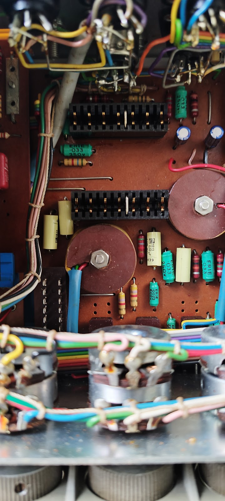
    C3 & C10  high-lighted on the Quad 33 motherboard
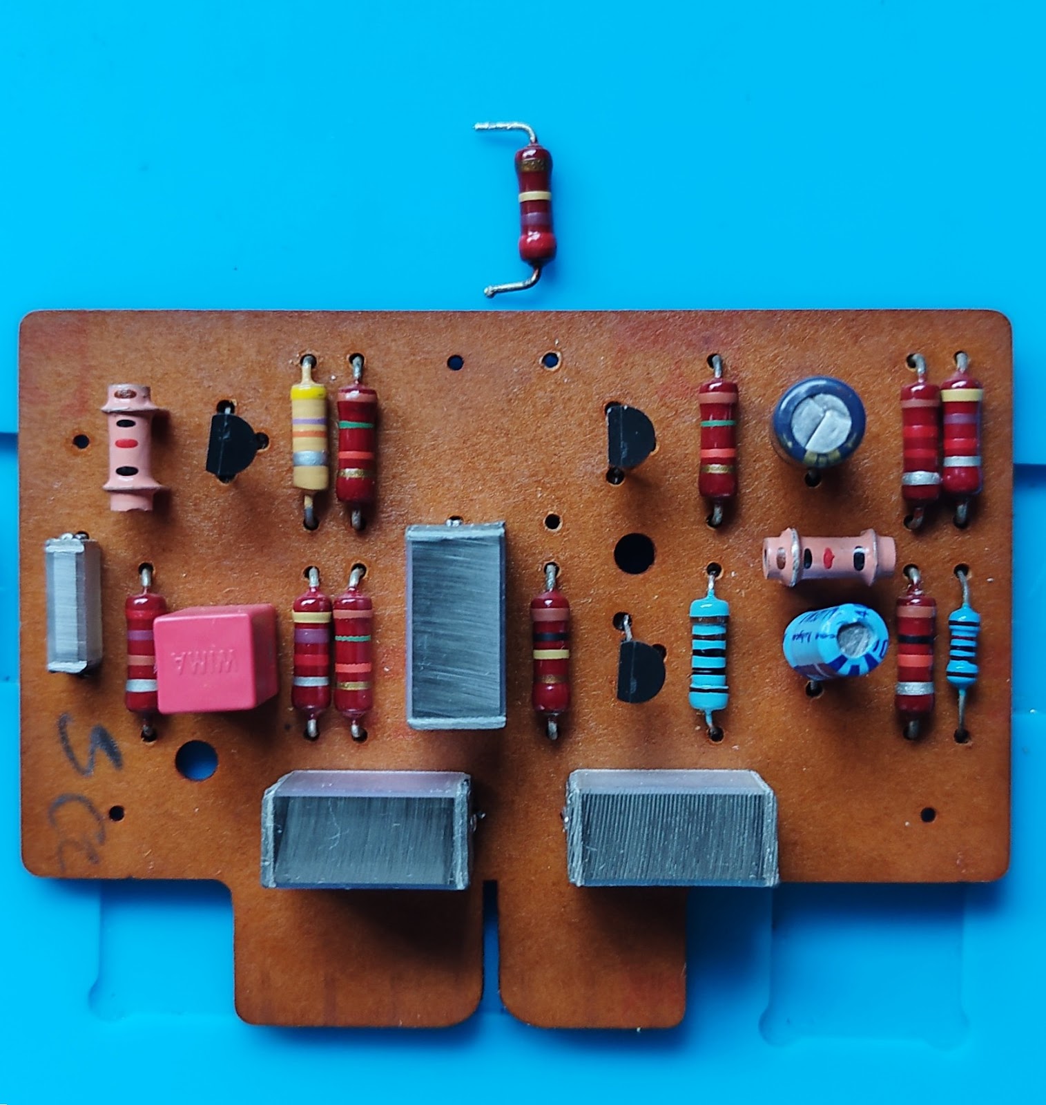
    C3&4&9&10 replaced on the Quad 33 motherboard


  11. Will replace C3&4 on the LHS and C9&10 on the RHS channels, to ensure "sonic matching" since there is a potentiometer in between these capacitors (on both channels).
  12. Next I returned #1 boards and reseat the original amplifier boards (from #2) back into the Quad 33 ... 😕again no sound from RHS??? However this time the audio moved when I swapped  the LHS and RHS amplifier boards.
  13. Therefore, there is a bad component(s) on the original RHS amplifier board.  Resumed testing components one-by-one using the DMM and transistor tester. Finally ... R406 was the bad component (270Kohm 1/4watt).
    Bad R406 270Kohm resistor on amplifier board


  14. Once R406 was replaced, both audio channels were audioable again. Had to adjust the balance slightly as the reproduction was just slightly off centered. Most likely cause is the use of different brands/make/wattage resistors on both amplifier boards - "re-alignment" task for another day...


Finally realised why Quad 33 #1 did not experience any issue of loss of audio on 1-channel - I had replaced all the axial capacitors on that motherboard long time ago as I wanted a unit to compare the reproduction difference when using original vs modern capacitors!!!


Sunday, June 1, 2025

FYI Quad 303 owners - Check the condition of your driver board capacitor(s)

 Hi everyone,

Please do check the condition of the electrolytic caps on the Quad 303 driver boards every once in a blue moon, especially the condition of C101.

C101 as per high-lighted, on the Quad 303 driver board pix from the service manual

I chance upon mine while investigating why only one channel was audible when using the Quad 33 from last month (since discovered had several problems).


Quad 303 #1

Please refer to the pix below.

C101 on each driver board - note the darken area towards bottom half of each capacitor


Even though the power amplifier performed flawlessly, the visually impacted C101 could be sign of a latent issue at large as these FC(s) were purchased from Element-14.

I troll the DIY forums for information regarding any similar observations. While I did not manage to locate any, I did note there were many reported issues originating from the PSU board. Since C101 on both boards were impacted, this had to be the common source of the issue!

Thus I obtained an updated Quad 303 refresh PDF from DaDa Electronics and followed the bias-ing procedure. 

Immediately discovered the issue - PSU was pumping out 74V and adjusting trimmer RV200 had no effect at all!!!

Testing TR201 using a el-cheapo tester from AliExpress shows that it was faulty and behaved as if it was 2 diode(s) which output to the 3rd pin - see following pix.

Result when testing TR201 on the transistor tester


Ordered a replacement BC441 as I already have the appropriate heatsink. While awaiting for the BC441 to arrive, I changed RV101 from 2K2 to 22K on both driver boards (since the S/N of the unit was well below 11000) as per recommend by the PDF.

After repairs


Since I have a few spare 470uF 35V lying around, will use them 1st to "test the waters" till I can purchase proper audio EC capacitors for C101.

Upon installing BC441 as TR201, the PSU was initially outputting 60V. I then followed the bias-ing procedure and obtained a result close to the recommendations.


Quad 303 #2


Checking #2, found the same C101 issues as well. 

The PSU on this unit was outputting 78V+!! Adjusting RV200 could only bring down the voltage by decimal points! Hence power-ed down the unit immediately and re-position the trimmer to mid-point.

The cause for unit #2 was not TR201, as checking the transistor via the el-cheapo AliExpress tester indicates it's working fine. 

Proceeded to test the various components on the PSU board via a Digital Multi-meter (aka DMM) which then reveal diode MR200 was in open status. 

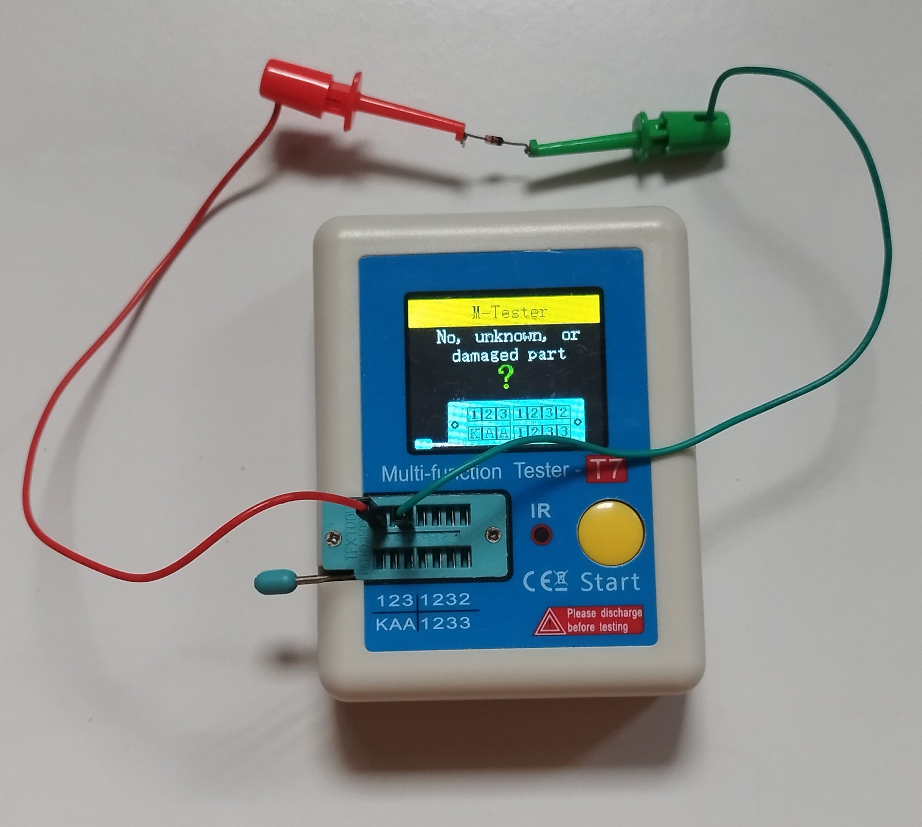
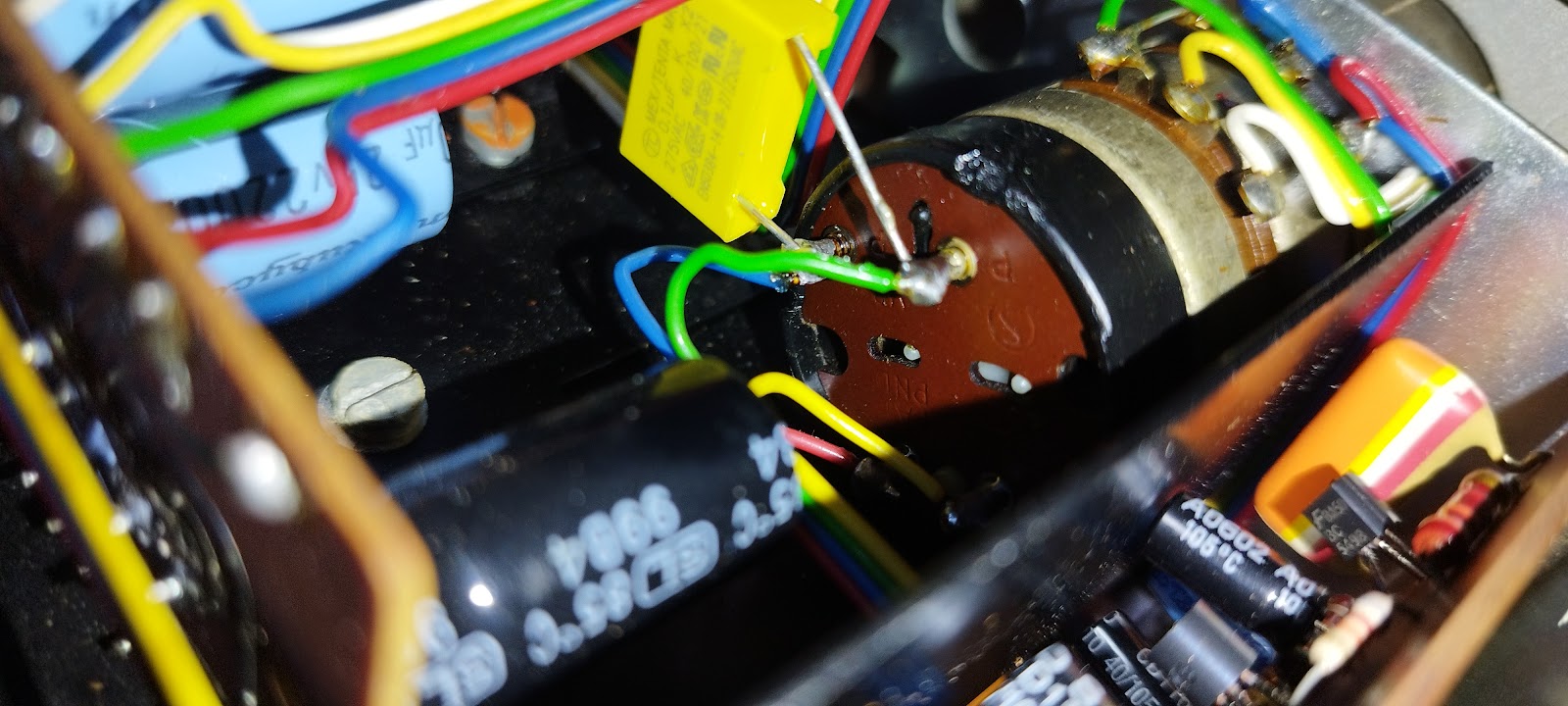
Tester confirm bad diode detected during DMM inspection of the PCB


Replaced MR200 with a 1N4004 diode, as per suggested by the PDF.

The diode, MR200 on the Quad 303 PSU


Took the opportunity to change RV101 from 2K2 to 22K on both driver boards since the S/N of the unit was well below 11000. And used the spare 470uF 35V until I can purchase proper audio EC capacitors for C101.

Upon power up, voltage was 76V+ but could be reduced via adjusting trimmer RV200. Again, followed the bias-ing procedure and obtained a result close to the recommendations.


Quad 303 #3


Will review unit#3 at a later date as it's a spare and in storage ... TBC


Thursday, May 8, 2025

DIY Hack for broken Quad 33 Balance control "U"hook

Took my 2nd Quad 33 (refreshed Electrolytic Capacitors only) from storage only to discover the balance control does not work. 

After doing due diligence inspection of the Quad 33 boards and spraying contact cleaner everywhere, saw the broken "U" shape hook at the end of the balance control slider. I may have tried to move the slider too hard as it was pretty stiff, breaking that fragile piece of old plastic in the process.

From the internet, as there is no pix of the slider in the service manual


Tried to purchase a replacement but could not locate any spares for sale anywhere.

Then I had an idea - why not use a strong string of sorts eg fishing line, badminton racket string, or alike - tie a knotted loop around the protruding metal piece (maybe adjust so closer to edge of the slider) and tie another knotted loop around the remaining plastic piece eg resulting in a figure-8 shape. 

That did the job - see the pix(s) below. 

1st knotted loop, around the protruding metal piece

2nd knotted loop around the remaining plastic piece

Will perform a proper replacement ... someday😏


Note: Spraying contact cleaner into the balance potentiometer did restore smooth operation

Wednesday, April 9, 2025

Quad 5-pin DIN connector pinout

From internet


Recently dug-out my Quad 33 for a run, only to discover one of the 5-pin connectors did not work properly - only RHS had audio.

Had been a while since using the Quad 33 and was at a loss regarding the pinouts😓.

Thankfully nowadays there is the internet and after some searching found the above - had forgotten the information was at the back of the unit itself😳

For those in the same boat ...😁

Tuesday, October 11, 2022

DIY PCB for dual mount TDA1541 (***Part-1***)

Could not resist getting this DIY PCB to attempt simplifying twin mounting the TDA1541/A since there has been quite a few notes of it being done by well-known manufacturers eg Accuphase, Nakamichi, to deliver better DAC processing resolution etc.

Have always deferred the "twin mounting" as preferred a less tedious or permanent solution ... until now!


Kit supplied components, top view


Kit supplied components, bottom view

Kit supplied components, with the row of pins slotted into position only


Kit supplied components, slot into place and straighten using DIP-24


Kit supplied components, slot into place and straighten using DIP-24 and held in-place by zip tie, before soldering


To be continue ...

Kenwood KT-5020 (***Follow-up***)

Was window shopping in town when I stumble upon this little gem.


Kenwood KT-5020


FMTUNERINFO rates the KT-5020 as a top-10 contender among all the devices it has tested over the years. Naturally pickup it up as it was too good an opportunity to pass over.

The tuner has a simple, intuitive and easy to use interface with auto-tuning and set of A/B memory presets for both AM and FM - really ... no manual required.

As per reviewed in stock form by FMTUNERINFO, the KT-5020 is indeed an excellent performer which delivers with confidence!

May consider recapping it at a later stage according to the suggestions in the MODS sections of FMTUNERINFO, once I have spend time listening to the KT-5020.


11Oct, 2022


Finally opened up the KT-5020 - no fancy capacitors in-sight (just brown ELNA;s) but yet able to attain a top-10 spot in the shoot-out performed by FMTUNERINFO!!!

Single motherboard of the KT-5020

Saturday, September 10, 2022

DIY CDM-9 tray gear replacement

Was helping a friend replace the aging CD player tray gear on his Arcam Alpha 5 CD player ... did not expect I would need to dissamble the enitre machine to get the task done😩

The Arcam Alpha 5 uses a CDM-9 mounting mechanism and because the Arcam box is a solid part ....

New tray gear on LHS of the pix

There was really no choice as there was no release mechanism for removal of the CD tray itself, to simplify removal of the CD mount mechanism eg alike VAM12.1. The gear is secured by 2-torx screws on the bottom of the CD mounting mechanism. The CD mounting mechanism was in-turn then secured to the motherboard by 2 screws covered by hard plastic (after the threads)!!!

LHS is the new, vs, the removed CDM-9 tray gear on RHS


TIP - Remember to grease the shaft on the CD mounting mechanism before inserting the new gear into place ... use suitable grease which will not "eat-into" the plastic, available from electronics part shops

Monday, August 22, 2022

REVISIT#2 - DIY TDA1541A DAC

Recently retrieved the unit (REF: http://myoldvintagehifi.blogspot.com/2018/04/revisit-diy-tda1541a-dac-with-usb.html) from storage for a listen, only to discover that it did not sound as clear nor as precise as my Meridian 600-series DAC. I do not expect it to best the Meridian but the reproduction was clearly "more muddle" than it could have been.

Hence I Google-d for TDA1541A DAC schematics and upon review, discovered the capacitor values deployed in the output stage (where the opamp are) can vary drastically, depending on implementation - section encircled by yellow line in the pix below.

Output section with op-amps


Cross checking the Google-d information for the capaciitors deployed in the op-amp section, vs,  the values etched onto the op-amp section of  the PCB, these values differ drastically. And examining the capacitor themselves, again result in different values than the etched values on the PCB next to the capacitor itself!😒 Well, what can I say - I did buy it from a China based eBay seller....

For the record, all the blue capacitors deployed in that section are Vishay 1nF 100V. 

After some basic tracing of the PCB connectivity, I decided to try replacing the encircled capacitors in the pix below with Wima 100pf 100V.
1st Capacitor to be changed in op-amp section


Opon power-up, output clearity and realism (being less muddle-d) has been drastically improved ... will update after I have an opportunity to "run-in" the change.


Thursday, July 1, 2021

TIP - Effective USB powered FM signal amplifier

Had previously bought the following USB powered FM signal amplifier, as part of a antenna kit, to overcome the loss of access to the building FM antenna facility (REF: http://myoldvintagehifi.blogspot.com/2019/02/alternate-analogue-fm-reception-for.html)

I can definitely recommend this USB powered FM signal amplifier as it is works very well and is a cost effective solution. Even bought a 2nd unit for another tuner in the house!

It is basically the no-frills version of the FM signal amplifier which was originally intended for use in motor vehicles but altered to draw power via USB. Hence there is no need to buy the expensive radio signal amplifiers or antenna kit as the total cost for all the items in the pix(s) below cost less than the price for a single signal amplifier unit (only) at the local shops!


Note - May need to purchase connector adapter(s) to enable connectivity and an external antenna


For the 2nd installation I used a salvaged WIFI 5dB antenna, mounted on a external SMA-connector type WIFI antenna kit - see items below. Works great and the solution does not cost "an arm-and-leg"😁

Salvaged 5dB WIFI antenna on SMA mount

Bare SMA connector and mount kit fitted with adapter(s) for connecting to tuners 


Blue-tooth receiver with audio player and ESS DAC

Just received my new Trasam DAC2PRO earlier this week. 


Trasam DAC2PRO (silver) directly connected to the Sansui B-2101 amplifier


The DAC2PRO provides a blue-tooth upgrade to my existing hifi setup with RC and remote volume control.

In addition, the unit has the ability to playback FLAC, MP3, WAV, M4A encoded audio via a ESS based DAC. The on-board DAC processes input received via a soft selector for COAX, OPT and Blue-tooth😑.

I ordered a unit with audio quality components from the Chinese eBay equivalent - came with black colour Nichicon EC capacitors on the power circuits and a OracleII-02 op-amp on a DIP-8 mount (phew!). Rest of the components are SMD types.

Was quite disappointed there was no MUSES op-amp provided with the unit. Hence I ordered a MUSES-8820 and 8920 as these are quite affordable nowadays as these have been superseded by the newer (and more expensive) MUSES-01 and 02.

Will update with more pix(s) and feedback of the sonics with the Oracle vs the older MUSES op-amps once I have the opportunity to perform the review.

In the meantime, I will have a play with my new toy 1st....😀

Tuesday, May 18, 2021

Changing OP-Amp(s) on the DIY TDA1541A DAC (***Update***)

Since spending more time online nowadays (due to COVID resurgent worldwide), I chance upon some good deals for better OP-Amp(s) from overseas. This was a good opportunity to swap-out the default NE5534P on my DIY TDA1541A DAC with USB interface, as I have (more or less) done all I can with capacitor replacements - not in the blog but had swap out the output capacitors for Elna Stargates since the last post for the DIY DAC.

Have decided I was not going to spend silly amounts on buying blackcaps, silver cabling or anything fancy of that sort since I wanted to see how far I can improve the unit on a budget. So will not splash out on Burson op-amps, MUSES-03 or alike.

Thus have ordered some Philips NE5534P, JRC 5534 and  OPA604AP.

Will update once I received the goodies and can do some swap-outs tests.


21Jun2021


Received the above op-amps and did the swap tests.

Ti NE5534 The default which came with the kit. My personal take is that it was the "Jack of all trades" but "Master of None" with a skewed HF reproduction and bass which was not flabby nor tight.

JRC NE5534 The minimalist choice. Has better overall balance than the Ti but came with a "English"-like reserve. Again nothing really wrong but did not excel in any particular area(s).

Philips NE5534 Best way to describe this would be to say it's alike the "Toyota Corolla" of 5534(s). Prefer it over the previous version of 5534(s) but know I could get a better replacement.

BB OPA604AP Initially the HF sounded thin with non-existant LF. After a couple of days usage, the sound stage surfaced. After another few more days, the most astonishing thing happened - the DIY DAC now sounds pretty close (after the unit has warmed up) to my Meridian 602 when performing an A-B comparison, with a slight difference in the output volume during the A-B comparisons.


OPA604AP x 4 on the DIY DAC PCB


Yup, left the OPA604AP(s) in-place  ....😁

Saturday, October 3, 2020

Proof-of-Concept (POC) of another alternate CD transport (***Update***)


Old Sharp VCR with TOSLINK for audio output


I obtained the old Sharp DV-NC80 from a neighbour who converted to using a cable video streaming service. The unit had a CD/DVD player with TOSLINK output and I was curious as to it's viability as a transport.

Hence I tried using the Sharp as a transport paired to the Audiolab 8000DAC. Much to my surprised, the resultant audio reproduction was clean and the Sharp performed much better than the Samsung DVD player when used it as a CD transport!!! Does sound pretty decent when amplification is via the EL34 integrated valve amplifier pushing the DIY LS 3/5A with AB1.

As there was no remote, I could only use the Sharp to play a CD end-to-end. Due to it's age, I do not think the Sharp will last for many more years so will not search for it's RC and just enjoy it while I can.


UPDATE #1 - 11Nov2020


Out of curiosity I tried a putting some songs on a CD-RW and stuck that into the Sharp - much to my surprise (again), it played without issues....


Saturday, August 1, 2020

Pioneer F-223

I recently acquired a Pioneer F-223 digital tuner from a friend.

Front view of Pioneer F-223 with main portion of test cable for antenna on top of unit
View of internals from the top

Was surprised the F-223 was "Made in Japan" (on the label, on the back of the tuner). Not much luck Google-ing for additional information or checking FMTUNERINFO but did managed to locate the service manual at HIFIengine.

F-223 Made in Japan
Voltage selector on the bottom of unit, towards the front as indicated by arrow


 The F-223 has the looks of an average tuner for the era. Extremely easy to use without the necessity to go thru the manual 1st. A big bonus of the F-223 is the large number of memory storage for stations eg 24 per band. After a station has been detected, you need to press MEMORY followed by a storage location before the details will be kept.

Was considering recapping the unit but discovered the capacitors on the audio path (red-line in the service manual schematics) had been recapped using Panasonic equivalents when the rest of the unit had used the old fashion ELNA(s) throughout.

The tuner seem to be pretty good at picking up the signals of the main stations easily via the AUTO-TUNE facility using nothing more than a short piece of wire - see pix. It did not pickup stations such as 89.3FM but to be fair, I was just performing an initial test and it was not connected to a proper antenna setup. Believe the F-223 would perform much better if I had done so.

Using a short piece of cable for initial FM tuner testing

Surprisingly a pretty good unit which just works with above average performance.


Wednesday, July 1, 2020

Follow-up of DIY LS 3/5a (*** Update-1***)

As Singapore was in "Circuit Breaker" mode (aka govt movement restriction due to COVID-19), I had more time on hands (don't we all...😒) and could follow-up on some hifi add-on items for various (more or less) completed projects. 

One such "missing link" was the tweeter felt squares for my DIY LS 3/5a. 

In the past I did not purchase these tweeter felt squares since I had categorised them as a "nice to have but not essential" to complete the project ... and they were a little costly once you factor in shipping etc.

During my free time browsing the net, I came across the below which were made using wool, roughly about 5mm thick. 

True, the O-square may not be perfectly cut but for the price difference, I could cut them myself or just let them be- good quality material as well 😁 

Delivered with the solid rectangle to protect the "O" 

Attached to the DIY Ls 3/5a without adhesive - corners of the rectangle are held by the velcro on the LS 3/5a baffle


What's the effect on the tweeter output?

The O-rectangles "clean-up" (not clear-up) errant sound which were dispersing to side-way(s), resulting in pretty much total silence between songs and quiet passages👍👍👍


Monday, June 1, 2020

TIP - Internet radio for newbies

Since most of the world is in one form or another of COVID movement restriction scenarios, it is a good time to explore the world of internet radio - why limit one-self to only local radio content?

You can easily test the waters via websites on the PC such as the following examples which is just a small sample of available websites.


or simply enter internet radio online website on your favourite search engine.

Alternatively, you can download internet radio apps onto your smartphone from GooglePlay and IOS - best to monitor your mobile data usage, and, stream the internet radio broadcast to your hifi set via a stand-alone bluetooth box.

As one of the sites inform,

Over 30,000 Stations Worldwide. For free


Do explore and enjoy the various internet radio stations worldwide!

Sunday, May 3, 2020

Tips for implementing a secure Mesh WIFI setup

Since we are required to stay home more during the current COVID19 outbreak, decided to take the opportunity to inform of a MESH WIFI network (link to Wikipedia) I have setup in my home to eliminate WIFI blind-spots and simplify connectivity for the home (as well as the Android audio-video box for internet radio).

For most of the us, the following would be the typical home WIFI setup.

From Google ... why re-invent the wheel?

However the typical home WIFI setup is not ideal - the signal weakens the further you are from the WIFI router, irregardless of whether you are trying to access the old 2.4Ghz or newer 5Ghz channel(s).

You could add WIFI Repeaters into your WIFI setup but that means you need to switch to a different SSID for every different repeater you need to access (at different parts of the house). 

Furthermore, the fast WIFI Repeaters are quite costly - especially if you require a few to provide decent WIFI coverage in the house.


MESH WIFI was introduce to address the above issue(s).  In theory, with a MESH WIFI setup you can be communicating seemlessly via WhatsApp video chat and walk to all corners of the house without issues - WIFI signal strength will be good anywhere in the house.

The following would be the typical setup for a MESH WIFI network in your home. Number of nodes or slaves requirement would depend on the size of your home.

Image CUT&PASTE from TP-LINK 

Sounds to good to be true, right?

Well, yes and no. 

WIFI coverage will be good and speed will depend on the specifications of the MESH wifi you purchase.

You will lose many of the security facilities normally available on the "run-of-the-mill" WIFI wouters. For instance, most MESH WIFI will have only very basic firewall facilities (some don't). In addition, some MESH WIFI actually run slower when the security facilities has been enabled. Others may have some limitations if you require to run them in certain configurations.

Furthermore, most of the MESH WIFI units lack any decent (or any) "Quality of Service(QOS)" facilities which are bundled with most of the current "run-of-the-mill" routers.

No problemo ... there is a solution - please refer to the pix below.

CUT&PASTE from Google

As per the above pix,  I repurposed my existing WIFI router to became the "gate keeper" with all the security and QOS facilities enabled. Hence best of both worlds via the old and new WIFI routers.

NOTE - Some MESH WIFI routers will need to be setup in Bridge Mode in order to function properly when configured as per the last pix


Been using the above setup for more than a year now. No performance or security issues .... so far.


FYI:- I am not using TP-Link or Google WIFI products, the above pix are for illustration purposes only as I Google-d for configuration illustrations for the discussion


Sunday, December 1, 2019

Obsession with Digital-to-Analogue (DAC) converters?

A friend recently asked why do I prefer using DAC(s), to using a dedicated player as I seem to have gained a few el-cheapo DVD players as transport? My friend still uses a vintage Marantz CD-72.

The summarised the PRO and CON(s) after a long discussion are:-


PRO
- Using a DAC, your favourite sonic signature will be preserved

- Not necessary to use a expensive and/or hard to repair player to act as transport

- Unlikely to break down often as a DAC does not have many physical moving parts

- Can replace the transport with a decent DVD player that's pretty affordable nowadays since DVD players are no longer the flagship players

- Can be part of a AV setup as long as your Audio-Video equipment has a SPF/DIF output eg android box, streamer etc

- Much improved audio presentation as a DAC hifi component has been optimised for the sole purpose of production of audio only eg best example is the Marantz CD-94 being enhanced with CDA-94


CON
- When your favourite CD/DVD/transport dies, the cost for repair and/or replacement will be expensive

-  May not be able to rescue the player due to way most companies operate today eg stock min parts

-  Need to evaluate many players before you can find a satisfactory audio quality compromise (if not repairable)


I look at it is a way to "future proofing" my setup and preserving the preferred audio signature.

Tuesday, October 1, 2019

Another low cost DIY tube buffer kit (***Update#2***)

Bought a different version of the low cost DIY tube buffer kit to try.

The new toy uses two  Chinese 6J3 tubes, with option of US made 5654W(s). My initial purchase was with the default Chinese made 6J3.

The main PRO for this 2nd DIY set is more space around the capacitors in the audio critical path eg the yellow poly(s), permitting a much larger variety of potential substitution choices.

Initial kit purchased

Similar layout to the previous kit but with more space for swapping the critical capacitors

Uses non-mainstream EC capacitors on the PCB

The default 6J3 purchased with the kit

Assembled kit in-action 

This new kit has the same power requirements and input-output layout(s). However, the output volume for the new kit is much lower than the previous. The potentiometer output is even at low volumes and cames with a volume knob which also functions as a power-on/off switch. To enable more space on roughly the same footprint, the new kit uses SMD resistors which were pre-soldered onto the PCB.

How does it sound?

Best way to describe is as if someone enabled a "tonal normaliser" on the output😬.

When I contacted the seller, they assured using the US made 5654W would make a "night & day" difference. Many online reviews does mention the US made 5654W(s) are worth the upgrade. Thus I placed an order for a pair since these did not cost an arm or leg!

Will update next month once I received the 5654W(s) and give them a spin.


1Nov2019

6J3 (LHS) vs 5654W (RHS)

Been using the buffer kit with the newly installed 5654W(s) for past few days and can confirm they do produce a remarkable improvement over the 6J3(s). Received the 5654W(s) quite a bit later than usual and suspect that is due to the decrease in the number of shipments from PRC with the on-going trade-war between the two big economies. 

Thus did not have the opportunity to run-in the 5654W(s) properly before this update. At the moment I can safely say that the "tonal normalisation" has been removed. The DIY kit is beginning to sound like a proper tube component.

Will allow the 5654W(s) to settle in before deciding if to start substituting the capacitors in the critical path.


Late September 2022


Pix after "upgrade"


Was considering changing the default yellow 1uF as the sonic reproduction was pretty good but could be better.

Hence did not wish to waste proper quality capacitors for a "Proof-Of-Concept" evaluation.
Found a few of the 2.2uF poly(s) which was removed from other units, since it has long leads, was suitable as a candidate#1.

Will leave it for the moment for further listening, and, swap out with others for further evaluation.

To be update iagain n the future.