horz1

Saturday, August 1, 2015

Appropriate speaker cables for my DIY LS 3/5A with DIY AB1

Not sure if anyone else has similar experience with their LS 3/5A with AB1.

The combination was pleasing to the ears and even a musician friend was complementary of the presentation. However I felt the presentation could be further improved, especially if the HF was to be as fluid as that of horn or horn-loaded-tweeter.

Tried using the original QED and vintage Canare cabling but to no avail. Hence I search the market for used Van Der Hul MCD-352, as I had previously heard it on a friends' Celestion SL6 driven by a Plinius set. After some time, I did manage to acquire the VDH and it did provide improvements.Unfortunately the improvements were not to my expectations.

I then installed my original QED Silver Anniversary (not the XT) for comparison, since both are silver-type speaker cables. 

Viola!!! Everything fell into place when driven by one of my Quad FM3-33-303 sets. Yes, should have trial the QED Silver Anniversary 1st before searching for the VDH.

Another case of the solution being closer to home than one might think!


Wednesday, July 1, 2015

Sansui AU-20000

Sold my mint condition Sansui AU-20000 a number of years ago and did not have any photo's of it.

For those not familiar with the unit, please refer to http://www.classicaudio.com/value/san/AU20K.html for pictures.

From memory the unit weight about 22kg and was pretty retro looking with a lighted VU meter for both channels. Unfortunately you can not disable the lights, only the metering. Hence the VU lights can be quite distracting, especially in the night.

The AU-20000 was the top-of-line of the Professional Series, with had all the bells and whistles you can think off eg swap L-R channels. Operation was pretty straight forward but I prefer the ease of enabling the tuner from the AU-9900.

The buyer said it sounds like his newish MacIntosh. He was surprised the components were atleast 30years old! Inform him it would sound much better once he got it service and recapped. 

Why did I decide to sell this mint condition top-line unit, you ask?

The AU-20000 has an extremely fluid HF. Bass was acceptable but neither authoritative nor flabby, Would certain be improved after servicing. The AU-20000 was extremely gruntly as well - much much gruntier than I would ever require from it. However I did not find the AU-20000 reproduction to be as natural sounding as the AU-9900A. 

About a year after I sold my AU-20000, I met another seller (of his AU-20000) with similar feedback. Even so, the unit was sold within a day of posting.


FYI The following archive has details pictures of a AU-20000 restoration

Monday, June 1, 2015

Test - Streaming audio via Apple Airport Express

Was intrigue by such facilities when I visited the local AV show last year.

The vendors at the AV show were using a streaming service to demonstrate their wares - amplifiers and speakers. They would ask the listeners for preferences and initiate the demonstrations via a mini IPad.

Researching the above I decided to give streaming a go using an older model Apple Airport Express as we have an IPad in the house. This is because the small-sized 802.11n Airport Express are now reasonably priced. 

There are many free (but degraded) streaming service available. I settled on Spotify as my kids were already using it.

The following items will be required to make it work:-
- An Apple product (Android app to access Airport Express is not free)
- An Apple Airport Express (or alternative)
- Audio cable with 3.5mm mini-jack with L/R RCA outputs. or. optical cable with mini TOS to TOS connectors
- USB cable for printer connectivity (optional) to enable wireless printing
- Ethernet cable to enable the Airport Express to function as wireless router, bridge or repeater (optional)
- Register to choice of online streaming service or use playlist on your Apple device

Physical connectivity is straight forward. Connectivity setup requires a bit more work. Please refer to manual or online tutorials for the connectivity setup.


Once setup, I can control the volume and songs to be played from the iPad. There was a 1-2second delay between issuing the command on the iPad and hearing the results from the amplifier.

Quality from the free streaming service was reasonable with some adverts in-between material every once in a while. We did experience buffering time-outs when the iPad was not accessing the wifi via AC-protocol. My wifi setup comprise of a ASUS RT-AC56S connected to a Huawei fibre modem (with fibre cable into the apt).

Overall the free streaming service was a good and convenient way to hear new material before committing to buy the CD ... Yes I still prefer the quality from CD after testing MP3 at high bitrates (320 and above) against the original CD.

Friday, May 1, 2015

Sony CDP-X7ESD with Marantz CDA-94 DAC

Was clearing the storeroom and came across the old battleship ... the X7ESD weight more than most of my integrated amps!!!

X7ESD as transport with CDA-94 as DAC
Since the CDA-94 was already on the hifi rack, took the opportunity to pair the X7ESD with the CDA-94 (previously with the CD650).

The X7ESD has been in-storage for atleast 3years. Even so, using it upon power-up was like it never left the hifi rack. Everything just works as expected. The CDP output volume was stronger than that of the CD650 and CDA-94. Reproduction from a familar CD thru the CDP was of very good quality, thought the HF was a little brighter than it should be. Switching to the DAC output, everything fell into place though the output volume was lower. In fact I was surprise to hear delicate items reproduced with natural clarity as well as bass which has not been evident before this occassion!!!

So much for the theory of a transport conveying 1's and 0's only, therefore the 1's and 0's are the same from any player!

In summary, the X7ESD pairs extremely well with CDA-94, as if they were made for each other.

The X7ESD, CDA94, G90X and ST333ESXII form a group in my collection of higher end vintage gear, with wooden panels on the sides.

Wednesday, April 1, 2015

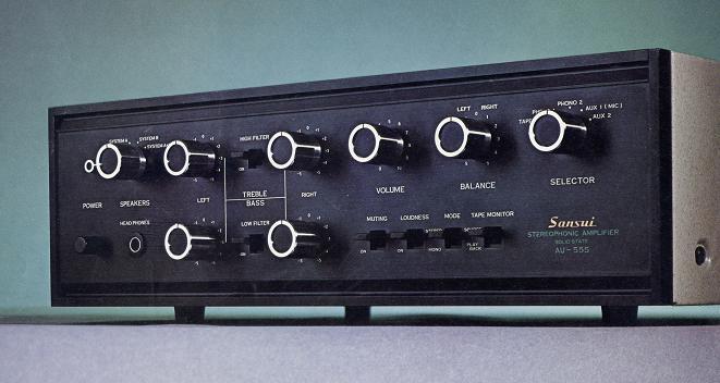
Sansui AU-555

Sold my prestine condition AU-555 quite a number of years ago ... still wondering if I should have let it go (with original manuals), or, keep after recapping it.

I know I have some pix of the unit but can't seem to locate them ... when you require them! Hence will use the following links to pictures on the internet 1st and update the blog once I do find them.

From Audio-Database

From Amp8

From memory the unit has a very nice tube-like presentation and weight more than it look. Output was pretty much balanced with a tad more HF than bass, I normally set the bass to +2 and rarely use the LOUDNESS switch. Nice bonus is the separate bass and treble controls for each channel. However there is no tone control bypass.

Main weakness was the lack of additional inputs, plastic flip switches which are hard to replace, speaker terminals using a actual screw which made changing speaker cables an exercise in-itself, and, no speaker protection during power-on/off. 

Otherwise operating the unit was quite a pleasant experience as the dials had a nice feel to them.

Normally had the volume to just before 9 o'clock before it was at a nice easy listening volume via the Meridian A500 or the Celestion SL6s.


Sunday, March 1, 2015

TDA1541-based CD player vs TDA1541-based DAC

Finally had the opportunity to setup these two vintage units as a pair - the Philips CD-650 as transport and the Marantz CDA-94 (reviewed by DutchAudioClassics) as DAC.

Philips CD-650 as transport and Marantz CDA-94 as DAC

The Philips CD650 has been recapped (some new caps with different values) according to suggestions@DIYAUDIO (no other modifications).

The Marantz CDA-94 has been recapped using better quality components only - original values are used.

The Philips CD-650 and Marantz CDA-94 are connected via (vintage) Monster Cable Interlink-400 to the Sansui AU-G90X. Digital content from the CD650 is delivered to the CDA-94 via a Klotz OT206 digital coax cable.

How do they compare?

Initially no difference upon usage straight from of storage.

After a week or so of continuous usage, the differences became more apparent. Even so, the differences would only be noticable once you turn up the volume past 8 o'clock on the Sansui.

The CDA-94 is as per the review on DutchAudioClassics - in short delivers to high expectations!

The CD-650 seem possess a slightly larger HF headroom and just a tad more aggressive in it's presentation. Reproduction from both are realistic and 1st rate!

I find myself preferring one to the other, depending on the music genre. Even so, both are very competent implementation(s) of the TDA1541 DAC.

Sunday, February 1, 2015

DIY - DIN input cable for older Quad(s)

Apparently these components are getting quite nowadays. Even the cabler(s) I frequently use are no longer interested to restock the 4-pin and 5-pin DIN (half moon or 180-degree) connectors once their stock run out. They inform there is not much interest in such items nowadays. 

Since I was in the Sim Lim area, decided to check out electronic part stores for the availability of the 4-pin and 5-pin DIN connectors (required by the Quads), as well as the availability of the female RCA connectors. As per informed by the cablers I frequent, these items are becoming rarer nowadays. Most shops do not stock them any longer. If you do locate stock, these tend to be the lower quality components eg discovered the DIN connectors with black plastic covers tend to disintegrate  after some time. Hence I try to avoid these when possible.

Here's an example of the required cabling - my older cable.

Thursday, January 1, 2015

DIY - Replacing broken glass (glue-on) on vintage tuner

Finally had time to replace the broken glass on the Sansui TU-9900.

Will not be using the other Sansui TU-9900 face plate (sent by the seller) as I maybe relocating to another part of the world in the near future. Hence I bought a Perspex replacement from eBay for the job and save the real glass replacement for another day - the original glass parts are rare ... very very rare!

Removing the face plate was straight forward.

1. Power off the unit and disconnect the power plug from the AC socket.
2. Remove the dial(s) from the face plate. Torx screw drivers required. The volume dial uses a smaller screw.
3. Push all the buttons on the left side of the face plate in and gently pull out the power on/off switch.
4. Remove the cover (8 screws;4 on the sides and 4 on the rear) to access the two screws inside, holding the face plate up 
5. Remove the two screws on the bottom of the unit holding the face plate to the chassis
6. Gently nudge the face plate away from the chassis
7. Put the face plate onto a soft surface eg towel, newspaper, with the face facing down
8. Use a bottle of electronic contact cleaner spray - similar to the one I am used. Do use the long nozzle provided
9. Spray onto the edges of the glass in very amounts eg just enough for it to get under the area of the glass. This is done to ease removal of the glass which has been secured to the face plate with double-sided adhesive 
10. Leave for a minute or so and then use a pair of pliers to assist with removal of the broken glass - it should just came off with a gentle tug - mine below
Glass after removal from the face plate
11. After ensuring all the glass fragments has been removed, I then use my fingers to remove the old double-sided adhesive from the face plate
With the removed original double-sided adhesive
12. Then use tissue or cloth to clean up the remaining fluid and let it dry.
13. About 5-10minutes later, I took the perspex replacement to position it into the face plate - DO NOT REMOVE ANY OF THE ADHESIVE sides yet.
14. Ensure the grooved edges of the perspex is facing into the face plate in the correct position before removing the adhesive protectors around the edges and pressing the perspex onto the face plate eg verify the 2-holes on the perspex are in the correct position
15. Once completed remove the rest of the coverings on the perspex and reassemble the face plate onto chassis eg reverse order of the dis-assembly
16. I now have the below

After perspex replacement
Looks great ... again!!!


Monday, December 1, 2014

DIY - Increasing number of inputs on vintage sets

I like using my vintage Quad 33-303 combo but was often frustrated by the need to disconnect-reconnect different sources due to the limited number of inputs on the 33 aka TAPE, DISC1 and DISC2.

Checking the internet, the total cost for proper input expansion boxes would be quite prohibitive since I would require a few such units for my numerous vintage sets.

I have a similar issue with speaker selector boxes .. for another post in the near future.

Then I came across the AV selector below and thought, why not try it?

Top view
View of the output RCA(s) to the amp, pre or processor
View of the possible input RCA(s)

Operation is simplicity itself. Connect the LEFT&RIGHT RCA(s) on the OUTPUT to your PRE or Integrated AMP. Then connect the desired Inputs to INPUT1/2/3 and use the selector accordingly.

An example is the below when deployed on my Quad 33-303 set.


Connecting various inputs to the Quad 33
Noise? Crossover "leakage"? Loud crackle when using the selector?

Been using it for a few weeks now and no sign of any undesirable issues or sounds yet ... you would not even suspect the AV selector was in-place unless you peered at the back of the set!

Saturday, November 1, 2014

Revisiting the Marantz PM-45

Recently stumbled upon the service manual for the unit. Hence time for a revisit.

In the past I had recapped the unit by only swapping the capacitors with better quality equivalents spares (I had on hand) on the main amplifier board.

After reviewing the schematics, it was quite apparent the key area for improvement was the amplifier board - rest of the circuitry adhered to the K.I.S.S philosophy.

The following pix is for the amplifier section of the Marantz PM-45 from the previous post.

Amplifier section from previous post
There were differences in the amplifier section vs the schematics for my unit??? Maybe late production changes?

Top view after 2nd recap
Close-up of the recap area

Important signal path changes
In the last pix above, the red and yellow outlines indicate changes which are necessary for converting the PM45 into quite a decent unit!!

The yellow outlined items are the new changes introduced after the previous post. The yellow box on the RHS shows that the previous EPCOS replaced with WIMA equivalents. Previously the EPCOS replaced the original green poly(s). These poly caps were not present in the schematics of the service manual.

The yellow box on the LHS required better quality 10uF 50V EC - used Panasonic FC.

The red outlined items on the LHS originally had 470uF 6.3V but were 220uF 6.3V in the service manual. Cause for the extra warm sound. Hence I replaced them so with United Chemicon 220uF 6.3V.

The red outlined items on the RHS were as per previous post (Nichicon 100uF 16V). I added 153J poly bypass to them, to permit HF to pass thru.

The results were startling with the above changes.

Note: Other EC caps on the amplifier board need not be audiophile caps - any decent quality EC will do as they are not in the signal path.

Wednesday, October 1, 2014

DIY TDA1541A DAC with USB interface (***Update#3***)

Bought the following DIY TDA1541A DAC for a test drive as always been curious of the reproduction quality from such products.


DIY chasis with everything inside
Size comparison against a CD 
Rear view
Initial impressions of the purchase? 

The unit was sent via a double-box cocoon. Superb built quality with a solid feel.
Layout within chasis

Works fine once the necessary connectors were in-place. Source was the el-cheapo Samsung DVD ($39.90 from a local supermarket chain) via SP/DIF. Initially connected to my Accuphase and later to the Audiolab 8000A to see if there were any difference in the quality of reproduction with different amps in play (no difference). Meridian A500 speakers were deployed. 

Close-up of the stars

The DIY runs a little warm as the chasis is an enclosed box. Only the red LED is in-used eg indicate power availability, although another two LED(s) were available on the faceplate. Looking about the motherboard, many Chinese brand EC(s) were deployed. Very few EC(s) were ELNA Stargate and Panasonic FC.

Initial impressions from the DAC (straight out of box) reproduction was an off-pitch with a bias towards the HF. After a couple of days, the DAC began to sound right. A week later, I can't help but to BE IMPRESSED!!! 

Reproduction was good enough to give my Marantz CDA94 a run for the $$$. Of course the CDA94 wins  hands down since it has dedicated power supplies, dedicated clocking board, etc. But for the total cost ... you can't help but to be most impressed by the reproduction capability of the DIY! 


1JAN2015

Finally managed to obtained the Philips version of the opamp(s) to replace the TI 5534.

WHAT A DIFFERENCE!!! Vocals are now beautifully reproduced with realistic depth and detail!! 


8MAR2015

I added a Wima 0.022uF bypass to each of the output capacitors which are located just before the output RCA jacks. 

This was done to lift the super thin veil from the DIY TDA1541 reproduction. The effect of the bypass can be heard after about 30min of usage, resulting in a bigger HF headroom.  

Next change would be to replace the Chinese made caps with my preferred ...


27Mar2015

Finally replaced the Chinese made 2x330uF 16V at the output stage and the 10uF 50V from the input with Panasonic FC equivalents. Must say the Panasonic FC replacement(s) made quite an impression as the Chinese made caps tend to be produce flabby bass.
Chinese-made caps replaced
Philips BC 0.027uF bypass on the Panasonic FC 330uF 25V output caps
Panasonic FC caps added to the final output stage (next to RCA)

I used long leads on the bypass(s) as the board is mounted on shorter screws towards the back where the RCA(s) are. Otherwise would not be able to place the board onto the chassis.

Monday, September 1, 2014

Refurbishing a Quad 303 on behalf

Recently an acquintance requested for assistance to refurbish his 303.

Externally it was in near mint condition.

These are the pictures of it internals.

View of the components on the top of the chasis
PSU board

Original RCA transistors
Condition of the large caps - one leaked with another two on the way (orange dots forming)
Original condition of the internals below the chasis
Close-up of the driver board with EC spillage

After recap and upgrading
The PSU board was functioning properly despite the damp looking surface. No humming from the transformer or any additional spillover near the PSU board. The PSU board output voltage was a bit higher than expected ... maybe cause of the large caps leakage after many years? After rebiasing the output voltage was stable over the period the unit was with me.

Only cleanup was necessary on the driver board with the spillage as the components seem to be within specifications - surprisingly!!!

The original 2x2000uF caps for power were replaced by a single 10000uF 100V United Chemicon - more than adequate for the purpose (proposed by another European electronics company). The 2x2000uF 100V caps for supplying power for audio purposes were replaced by 2x10000uF 63V Rubycon with a bypass (on each) for bass extension.

The carbon resistor on each of the driver boards were replaced with a metal film. A ceramic cap was replaced with an equivalent value silver mica. The EC on the 303 boards was recapped as per my other 303 except the EC utilised in the this case, were ELNA Stargates. 

Sounds great after the aging components has been given a new lease of life - clarity with detail across the board. Bass reproduction is now tighter and sounds more realistic.


Do note the internal cabling tend to be brittle. Hence please handle them with care

Friday, August 1, 2014

Leak Stereo 30+ (Unit#1 - with speaker output modified)

Like Harold Leak's other transistor amp's, the Stereo 30+ was made to sound like a valve unit.

Front view

Only the speaker connectors were modified by the previous owner. Paint work on the unit gives away it's age. Neither effect the quality of reproduction in any manner or form.
Rear - modified speaker connectors

One PRO is the unit was optimised for PHONO as there are Gain selectors etc on the back of the unit. CON(s)? The RCA connectors on the back are quite close together.

Rated at 15W RMS per channel, it is quite grunty and was able to drive the Mission 753 properly via the QED Silver Anniversary speaker cables. Sounded dull using my usual copper cables. To the fans of the 753, it is well known to be quite a power hungry unit which requires a high current amp to obtain the best from it.

This little gem was made to high standards as the quality of the components are superb - still the original parts!!! Upon a glance, the internals look pretty alike that of the Delta 30. Inspecting the circuit diagram on the internet shows very minor differences.

The Stereo 30+ does shine when connected to easier to drive speakers eg the Meridian A500's. So much so a visitor who came to buy my Musical Fidelity X10D was mesmerised by it's quality of reproduction - he thought it was a tube amp. Quite a complement coming from a tube amp owner. Speaks volumes of the Stereo 30+!!

When doing a brief search on the internet, notice many of the Leak Stereo-series are popular in Europe for driving the high-end dual-concentric Tannoy's.

Tuesday, July 1, 2014

Mythos Audio Vaccum Tube Monoblok


A friend's friend bought this unit over for review.

Little or non-existant information was available on the internet. At the bottom of the monoblok, it is written German ...

The owner advises it was 15W RMS per channel, with output for 4/8ohms. Valves utilised are EL90 and what look like China tube version(s).

Power was provided from the external PSU unit to each of the monoblocks. 

Power on/off was silent - no thums.

The PSU was about 5kg and each monoblock about 3.5kg. 


PSU unit
When input is received, you see the green bars on one of the valves on the monoblocks - the bar appears from top and bottom at the same instance even-though volume was zero. This shows input was present.

Monobloks with volume control

PSU internals

Monoblok internal
The MKP(s) in the monoblock are a China made brand, Chi Da. And these monoblocks run HOT!

How do they sound?

Overall a pretty nice sounding unit. The HF was natural and fluid. Mid was very natural and well defined. Bass could be better but lack authority. 

Beautiful set for vocals.

And grunty enough to drive my DIY LS 3/5A with the DIY AB1 connected in-series, without braking a sweat!!!

Sunday, June 1, 2014

Sansui AU-101

Just remember I used to own this little Junior many years ago.

Didn't take pix(s) of my gear then, so please refer to the following pix from the internet for reference. My unit was as clean as this pix from the internet. I remember the wooden sides looked very nice on the amp but was not solid wood (upon closer inspection).

Pix from internet

15W RMS per channel and a lightweight at about 6kg if you compare to the other Sansui's of the era.

Sold it as it didn't have the infamous Sansui grunt and had to regularly turn the volume to 11-1 o'clock before the volume was normal (compared to other amps) on my SL6S. Yes understand the SL6S was not a easy to drive bookshelve!

Reproduction was transparent and full of detail. Bass was not plentiful and had to leave the BASS knob at about 2 o'clock.

Con was the limited number of possible inputs.

The buyer used it as a bedroom set and advised the phono stage was superb - he used a Lenco L75 for source.

Thursday, May 1, 2014

Mission 751

The following is a internet pix of the Mission 751. Sold mine many years ago and did not have any pix of it.
Pix from internet
Bought the 751 as could not resist the good deal for it. I remember the 751 was lighter than my main speakers at that time, the Celestion SL6S. The 751 was also slightly shorter than my SL6S, with the SL6S being just a tad wider. However the 751 was much deeper physically than the SL6S. Cabinet construction was solid.

I remembered my initial impressions of the 751's reproduction - initially sounded neither here nor there. After a few days, the 751 started to sound right. A couple of weeks later, the 751 reproduction was actually quite  decent. Only issue I had was the clarity of HF  - details were not forth coming as the SL6S ... probably due to the plastic dome protector on the tweeter as per the Mission 753.

Since I had the SL6S, I decided to let my go of my surplus and sold the 751 with the Pioneer A400, Pioneer F-225 and the Rotel RCD-965BX as a package to a friend.

Tuesday, April 1, 2014

JVC A-X2

Another of the integrated amps from my past.

Unfortunately no pix(s) of my A-X2... yes been quite a while since I had it. Hence please refer to the following links located via Googling for pix(s).

Front likeness
Specifications via Service Manual

The A-X2 has their Super-A circuitry and runs quite warm after 10min.

From memory the unit was quite grunty and was able to drive my SL6S without any issues. Reproduction was decent but with bias towards HF on the reproductions ...  found it to be a bit hard on my ears.

Discovered my unit to be quite sensitive to interconnect and speaker cabling, with a strong preference for the older version of the Monster Interlink-400 and thick copper cables for the speakers eg vintage QED black copper cables.

A common issue for the A-Xn (where n is a single digit numeric) series was the failure of a small capacitor in the power amp section. In my case, it was on the LHS.

Sold the unit a couple months after acquiring it (and repaired) since it was a bit hard on my ears.


Saturday, February 1, 2014

DIY - Reinstating original green backlit after lamp replacement on Audiolabs

Been some time since replacing the original backlit lamps on my Audiolab(s). 

Must admit - I really missed the original green glow of backlit(s). Currently the available replacements does not produce the original green glow.

As I had open up the 8000CDM (awaiting replacement tray gear parts), decided to experiment with alternatives - drawing inspirations from my Sansui TU-9900 eg using a coloured filter of sorts. 

I decided to try using coloured drinking straws.

Sections of drinking straws for the experiment

After cutting them to a suitable length (and trimming the larger straw), I inserted the "candidate(s)" into the lamp holder areas to test, a set at a time - as per below.


With coloured straws inserted

Thickness of the thinner straws were simply too much for the lamps. Hence the results made the display hardly legible - must be within a meter???

Results from the larger straw were most pleasing but dimmer than the original. Definite improvement over the ugly yellow-ish alternative.

8000CDM display after adding filters

8000T display after adding filters

Will continue to search for a better alternative in the future ... until then, these will do just fine!

Wednesday, January 1, 2014

DIY - Tray gear replacement for Audiolab 8000CDM (VAM version)

After many years of service, the tray gear of my Audiolab 8000CDM (VAM version) gave way.

Initially I thought the belt driving the tray loosen after many years of service. Replacing it did not resolve the issue.

You could hear the motor after pressing the EJECT button but the tray does not budge. Upon closer inspection thru the CD tray opening, I could see the issue was caused by the non-rotating gear indicated by the RED arrow as the tray was not moving.
Offending gear without "teeth"

The next challenge was getting to it!!! Documentation on how to .. was not exactly widely available.

After much mucking around and researching numerous other posts, I noticed similarities on the Audiolab since it does use a Philips VAM assembly.

This is the procedure for removing the tray from the assembly - No other removal necessary.

Please remove power cable before beginning

1) Remove the metal cover and gently extended the tray to the maximum
2) Then use a screwdriver or similar tool to press the tab at the opening indicated by the beige arrow
3) Now gently slide the tray out from the assembly - in the direction indicated by the larger green arrow

How to remove tray after normally extended (to maximum)
You will now see a removable cover above the gear, towards the front of the CD tray assembly - gently release the tab and pull up to expose the tray gears. You can now remove the rubber band and the gears - see items below.

1st gear from LHS is the "toothless" one

Leaving the following behind.
Top view

Front view
Where to get a replacement?

Am ordering a full replacement set (2 gear and the rubber band). Will update once I have receive the parts.

Am deploying the Samsung C370 as backup transport until the 8000CDM can be repaired. Must say am surprised by it's performance so far!!!


17Mar2014

Received the 3 replacement parts from an agent in China.

Luckily I ordered additional belts as the item which was packaged with the gears was a little larger!

The good old reliable is back on-duty again