Saturday, November 20, 2010

DIY - Tube Buffer (***Updated#2***)

I finally gave up trying to get my hands on a used Musical Fidelity X-10D and bought a DIY PCB based upon the infamous unit thru a DIY outlet.


Used my spare NOS Russian 6N23P-EV(s) for this project - as per my Musical Fidelity Tubalog. Other components include the Audiophiler and Wima's (red and yellow "bars") for signal path, EPCOS for non-signal path, Nichicon MUSE (outlet recommendation), and Rubycons.


I began using a regulated "off-the-wall" PSU 12V 500mA to power the PCB. Sounded terrible with much "audio breakage". When I contacted the DIY outlet, they informed the original design was based on a unregulated PSU e.g wavely line vs bar with 3-dots above on the PSU. Sounded much better once fed the proper diet!

Started tweaking since it is now operational. Initially used Nichicon Muse 1000uF 35V capacitors (light metallic Green) as per recommended by the outlet. Later replaced these with equivalent Multi-Comp (aka United Chemicon) on my 2nd iteration as there was no audible difference via my Leak, mod DVD2900 and HoneyComb speakers when I replaced them.
2nd iteration
The highs and mid-range sounds extremely nice. Bass was better than before insertion of the PCB into the circuit but a little "muddle round the edges".

On my 3rd iteration, I replaced the 1st two filter caps with a single Rubycon. The "yellow" Wima was replaced with a larger value Silver Mica.

Wundabar!!! Everything fell into place.
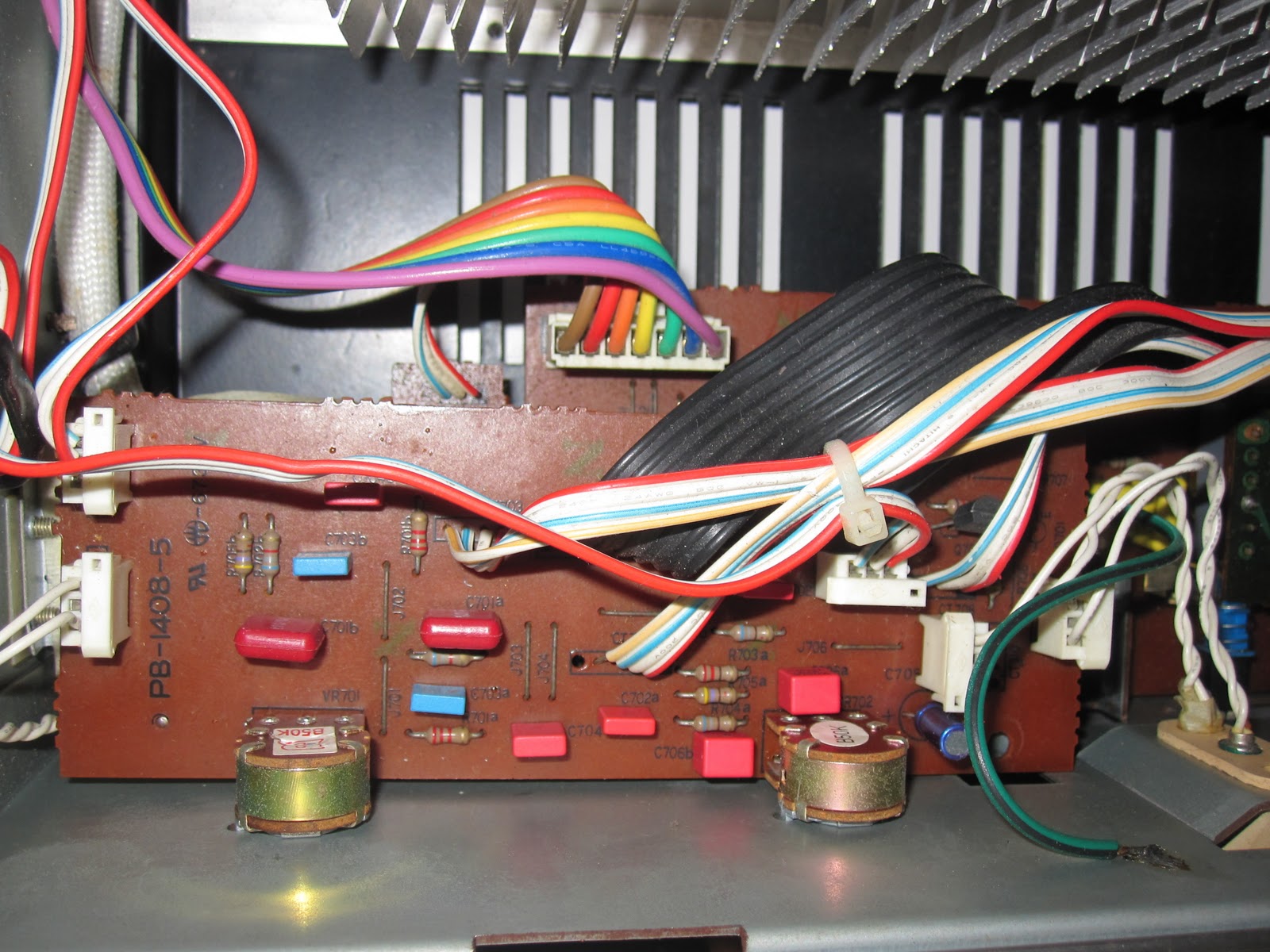
3rd iteration
Another view of 3rd iteration

Forth iteration. Replaced the Rubycon 10uf with Panasonic FC 22uf, as these were on the signal path. Sounds rich and life-like thru the Luxman L410, especially the piano pieces.

Update#1

I found the following schematic from the web and updated it with the changes made. The shaded area is the section which is in the signal path. Changes are in red text. The shaded area of the schematic clearly shows the audio signal path and I personally believe money should be spent on components in the shaded area. I tried better components in the unshaded area before and there were minimal improvements except for the upgrade of the power filter caps from 1000uF to 2200uF. I used 16V instead of the original 35V as I measured the voltages at these points and were below 16V. Using 2200uF resulted in a quieter background in the output e.g when you are next to speakers and no music was playing. And I did not use the 4007 diodes as per the schematic as I had many IN4004 leftover from my Quad 33/303 upgrades.
Schematic with changes

Update#2 - 27Sep2012

Both channels died and the valves do not glow anymore.

Checking the power section of the PCB reveals the 2.2R 2W resistor to be faulty and when tested shows a value above 400ohm.

Replaced the 2.2R 2W did the job!

Sunday, November 14, 2010

Bang & Olufsen BeoCenter 5000

The BeoCenter 5000 is a AM/FM/LW receiver with the BeoMaster remote.

Although conceived in 1980's, the unit remain stylish 20 years later.
Front view with FM reception
With hidden controls revealed
The unit weights a solid 10kg and has an internal fan in the amplifier section. The amplifier outputs 50W RMS per channel.
BeoMaster with hidden controls reveal
BeoMaster in action
Will not go too much into the unit as there is a dedicated B&O site online with detail information.

Am currently using the unit for FM reception as it seems most adapt for the purpose - the FM reproduction is simply superb!

Sunday, November 7, 2010

Musical Fidelity A1X

Regrettably, I had sold my pristine condition British made A1X without taking pix(s) of the internals.

Luckily, these are readily available on the internet. There are many articles on the mods, tweaks and recapping for the infamous unit so I will not go into those in detail.

As per other units in collection, I had recapped the A1X and obtained much improvement. Most noticeable was the definition and strength of the bass once the 4x10,000uf caps were replaced. And I put a bypass of 0.1uf (recycled poly) on the 10,000uf caps.

What I did discover along the way was not mentioned in any blog or website. After completing the above (as far I had searched on the net), I notice the A1X performed much better but was lacking in the ability to resolve details in the background ... it was definitely there but something was holding it back.

I reviewed the schematics (which are plentiful on the net - example below) and noted C15 and C16 are on the signal path.
Since I did not have the original pix of my A1X, I will use the following from the internet to illustrate the caps I am referring to e.g caps with 22 written and indicated by the arrow pointers in red.
sample with arrowed indicators
I replaced these 22pf caps with 33pf silver mica's. When tested, it sounded like a valve unit - warm, full bodied with all the details!!!

When the buyer of my (previous) A1X first heard the unit, he literally "fell head-over-heels" over it. He had previously heard other A1 and A100 units as well as the reincarnation.What more can I say ...

Tuesday, November 2, 2010

Luxman L-410

The L-410 is a Class-A bias (first few watts only) integrated amp and it really runs hot. The L410 is a high-power component, and, was previously able to drive my renown power hungry Celestion SL6S with ease.

Before re-cap, you could hear same off-key note from my Emi Fujita album (as per Nait). The offending component was traced to the pair of 'white translucent' 0.047uf non-EC cap on the pre-amp board.

After re-cap using better quality components e.g Wima, OSCON, Panasonic FC, Elna Audio, EPCOS, Siemens, Rubycon, Panasonic ECA, Elna Starget, Nichicon, AVX, silver mica and, Philips BC, the L-410 became truly transparent. Pairs well with my recapped Musical Fidelity Tubalog and Marantz CDA-94.

Please be aware of the bi-polar caps in the power amp section.

I believe the L-410 is Class-A for the first 8W or so (not documented anywhere) as once the volume dial passes just over 9 o'clock you notice it run not as hot as before and the "grunti-ness" increases - in the Luxman tradition of the L-510, etc. The other 'give-away" is the use of the "shark-fin" heatsink normally found in vintage Luxman's which run hot.

The following is a pix of an original L-410 (not mine) which was located on the net.
Original pix from internet
The following is my set after almost all the electrolytic (except the pair of 15000uf) and most of the non-EC caps were replaced.
View from front after recap
The following is the top view.
From top

The following pix are close-up(s) of the various sections, after they have been recapped.

Pre-amp board
Tone control board


Power amp board