horz1

Sunday, January 23, 2011

Altec Lansing ACS33 (2.1 for PC)

Although not really hifi, having a set of decent sounding speakers for the PC does help when you are listening to MP3, watching movies, accessing Youtube, etc - especially when you are used to a decent sound system!

I choose the Altec Lansing ACS33 (2.1) many years ago as I could not convince myself to invest on a pair of nice Klipsch speakers for the PC ($700+ vs about S$135 for the ACS33)!

ACS33 2.1 PC speakers
In stock form, sounds leans toward bass and can sound boomy. Details and highs were acceptable.

Hence I decided to investigate possibilities on improving the ACS33.
With bottom half of the sub uncovered
I removed 6 screws  from the bottom of the sub to reveal the above pix.

Closeup of PCB (after substitution)
Perform the following on the PCB:
  • replace the 1uF EC with a poly (yellow)
  • replace non-essential 1uF with poly (orange)
  • replaced 4x0.22uF (green) poly with 0.15uF Vishay BC (grey) - makes largest audioble difference
  • replaced the 2 caps for filtering power supply with Rubycon 2,200uF
  • add a heatsink to the voltage regulator as it gets hot
  • changed a few caps on the right side of the pix (though not really necessary)
The results?

Bass was firm and quite respectable. High and mids sound pretty decent (to myself)! Don't think I will be shopping for a replacement anytime soon...

Sunday, January 16, 2011

Sansui AU-7900

The AU-7900 is a well known unit in the "black face" line-up of the 70's. Perhaps best known for it's great phono stage.

A feedback at http://www.diyaudio.com/forums/solid-state/97232-sansui-intergrated-amp-su-7900-a.html speaks volumes of the AU-7900, especially since it was in a shoot-out by a stereo club!


Front
Internals from top


From bottom

Frankly I was quite surprised by the "kick" from the unit - at the volume setting in the pix, it had enough juice to drive the Mission 753 Freedom to a decent volume - many articles mention the 753 can be power hungry!

No recapping necessary as it still sounds great after all these years! Quality really stood out for something in the 70's.

Wednesday, January 12, 2011

Mission 753 Freedom


I finally laid my hands on the infamous unit. Weighting in at about 25kg each, it is a well constructed speaker.
753 without cover. Meridian A500 (with puppet on top), Quad ESL Pro63 in the rear and the Technics Honeycomb 

Upon initial listening using the copper cable transferred from the Technics Honeycomb, the 753 was disappointing - sounding compressed, glimpse of imaging, restricted headroom, with plentiful of flabby bass???

I was driving it using the Leak Delta 30 with only 15W RMS per channel but enough to drive my other well known speakers ... (not tried the Leak on my stored Celestion SL6s and the Pro63 yet)

Searching the internet, there were many comments regarding using an amp of atleast 50W per channel as well as mods to the crossover, etc to get the best from the 753.

What I did note was that the above setup while had plentiful bass and sounding compress, the 753 did convey the details as per my other speakers.

Hence I decided to try a simple experiment before going for the "works". I replaced the existing copper cables with my old QED Silver Anniversary (newer version has less than half the original core size).

Sounds almost top flight via the low wattage Leak Delta 30 using QED Silver Anniversary speaker cables!!! Like night and day by just changing the speaker cables.


Update

On the following week I managed to add a Sansui AU-7900 to my collection.

Tried pairing it with the 753 via the copper cable (since it has more power than the Leak). Bass was respectable but over-emphasized. The treble had the 'behind the veil'effect. Hence I inserted a bypass using a ROE 0.022uF for the 10uF and 6.8uF capacitor. And insert WIMA 0.33uF bypass for the 470uF capacitors. Furthermore added 2 layers of foam padding to the bottom cavity as the original was empty(?).

The cross-over unit looks a bit different from the pix(s) on DIYAUDIO and other websites as this is the Freedom model - without the 1,000uF capacitors and a simplified crossover board.
Original
After adding bypass to capacitors
Different view of cross-overs

Add 2 layers of foam

Speaker cable from the AU-7900 - more than enough 'juice'to drive the 753F

Been an hour and the sound is beginning to take shape ... vocals are sweeter and bass is firmer. Has the makings of a keeper!


Update:

Using the previous setup and copper wires, the 753F seem to slightly warmish. Bass became more firmer, voices were almost "being there" but there seem to be a very light veil still in-place.

Connecting the 753F via QED Silver Anniversary seems to be it. Everything is falling into place, with firm bass!!

Thursday, January 6, 2011

Quad 33 (1st unit of 2)

This particular Quad 33 is part of components from my 1st set of Quad 33, 303 and FM3.

Updates completed were largely according to Dada Electronic suggestions. Electrolytic capacitors used were mainly average quality. Very few Wima and Panasonic FC were deployed. Sounds suprisingly good though.
Front

Bottom and rear
The original plastic feet were replaced by rubberised equivalents, to prevent impacting other components during stacking.

Phono and Tape board

Top view

A bypass was added to the output boards as there was not much improvement in the HF response e.g seem to have been "cut-off". Used a green Wima for the bypass on the output boards. Sounded proper again after the bypass was added.

I was more adventourous with the 2nd Quad 33.

Sunday, January 2, 2011

Luxman T-240

This is the Luxman tuner which is of the same series as per my L-410.
Front
In stock form, the unit sounded nice but (a little) reserve. Due to age, the four power caps of 47uF 50V were replaced with 220uF 50V.

The following section were recapped with better quality capacitors - for the FM outputs.
Mod to FM output section
And the original 1,000uF 6.3V Elna cap was replaced with a Panasonic FC of equivalent specifications.

Sounds more open and realistic after the above recap. One of my visitors was pleasantly surprised when the FM station announcer did his job!!!

Sunday, December 26, 2010

Accuphase E-203


The E-203 is an early Accuphase which help Accuphase established themselves.

The unit runs hot as it is a MOSFET unit based into Class-A. More details at http://www.accuphase.com/cat/e-203en.pdf

Apologies as I do not have pix of the internals, as the unit is still in storage at the moment. The unit is well known to have an excellent phono stage - MM and MC.

Front of E-203
E203 as pre with Meridian 557

Sugden C51 (***Updated***)

The C51 pre-amp, together with the P51 formed the reference set for many reviewers in the 70's.

Sounds pretty good, even by today's standards. It is a very simple unit internally - apologies as I located these two pix in a photo album.

I will add the P51 pix to the blog once I find it in my store room (no kidding!!!).

There is a site dedicated to Sugden components so I won't repeat the praises sung there.
Front
Rear

Update

The following are the internals of the C51.

Top View
Bottom view

Was unable to locate the special grey-ish DIN cable which carries the audio signal and power between the C51 and P51 to enjoy the units . . ... the joys of having too many items in the storeroom!!!

Sony ST-S333ESXII

This is my Sony ES tuner. It is to be part of my set of matching components with wooden side panels. The other units in the group are the Sony CDP-X7ESD, Sansui AU-G90X and Marantz CDA-94. The other maching tuner is the Sansui TU-D99X.

Quality is as per expectations from a ES component e.g Nichicon Muse, Elna Starget, etc.

Sounds pretty decent - as good as reproduction from CD!

The website, FMTUNERINFO rates the ST-S333ESXII well and I quote .... "the ST-S333ESXII is a really close second to the Macs in sound quality, and just as good as the McIntosh MX 117"


Front
Rear
Right
Left
From top

Saturday, December 11, 2010

Quad 303 after recapping (2nd unit)

This is the follow-up of my earlier post for my 2nd Quad 303 unit which was purchased to enable bi-amping.

The Quad 303 is actually a well design unit which can sound superb after recapping with better quality components. The resultant sounds like a valve amp, as per many testaments on the web including  http://tech.groups.yahoo.com/group/quadhifi/message/11056

The external chassis was rusting. Hence I used AutoSol to clear the rust up before re-spraying. I chose the following colours as it does justice to the unit.
After re-spraying
The original power and audio caps of 2000uF 100V were replaced e.g Rubycon 10,000uF 63V for audio and United Chemicon 4,700uF 100V for power. Was previously using only the United Chemicon for both power and audio reservoir caps - sounded very nice as well. Only changed to the Rubycon for the audio reservoir cap as I have a requirement for both of my 303's to be the same. A 0.027uF Philips BC poly was used as by-pass on the Rubycon reservoir caps.
After large caps were replaced
The capacitors, trimmers and resistors were replaced on the audio and power boards with better quality components.
After recapping with better quality components

In addition I replaced a carbon resistor on each of the audio boards to "open up" the units, as there was still a slight roughness "round the edges" after recapping and re-biasing.  I decide to perform the replacement after some research on the internet.

For the DIY-ers out there, the above were perform according to suggestions by Dada and NetAudio. I choose to use Wima's and Panasonic FC(s). If you decide to revert back to the original Quad sound, it is quite easy. Just replace the big Wima visible on each of the above audio board (next to the 2 caps before the trimmer at bottom of the pix) with a different cap e.g Vishay BC (green) or Evox (grey). And put back the carbon resistor for the "roughness" in the sound quality.

Saturday, November 20, 2010

DIY - Tube Buffer (***Updated#2***)

I finally gave up trying to get my hands on a used Musical Fidelity X-10D and bought a DIY PCB based upon the infamous unit thru a DIY outlet.


Used my spare NOS Russian 6N23P-EV(s) for this project - as per my Musical Fidelity Tubalog. Other components include the Audiophiler and Wima's (red and yellow "bars") for signal path, EPCOS for non-signal path, Nichicon MUSE (outlet recommendation), and Rubycons.


I began using a regulated "off-the-wall" PSU 12V 500mA to power the PCB. Sounded terrible with much "audio breakage". When I contacted the DIY outlet, they informed the original design was based on a unregulated PSU e.g wavely line vs bar with 3-dots above on the PSU. Sounded much better once fed the proper diet!

Started tweaking since it is now operational. Initially used Nichicon Muse 1000uF 35V capacitors (light metallic Green) as per recommended by the outlet. Later replaced these with equivalent Multi-Comp (aka United Chemicon) on my 2nd iteration as there was no audible difference via my Leak, mod DVD2900 and HoneyComb speakers when I replaced them.
2nd iteration
The highs and mid-range sounds extremely nice. Bass was better than before insertion of the PCB into the circuit but a little "muddle round the edges".

On my 3rd iteration, I replaced the 1st two filter caps with a single Rubycon. The "yellow" Wima was replaced with a larger value Silver Mica.

Wundabar!!! Everything fell into place.

3rd iteration
Another view of 3rd iteration

Forth iteration. Replaced the Rubycon 10uf with Panasonic FC 22uf, as these were on the signal path. Sounds rich and life-like thru the Luxman L410, especially the piano pieces.

Update#1

I found the following schematic from the web and updated it with the changes made. The shaded area is the section which is in the signal path. Changes are in red text. The shaded area of the schematic clearly shows the audio signal path and I personally believe money should be spent on components in the shaded area. I tried better components in the unshaded area before and there were minimal improvements except for the upgrade of the power filter caps from 1000uF to 2200uF. I used 16V instead of the original 35V as I measured the voltages at these points and were below 16V. Using 2200uF resulted in a quieter background in the output e.g when you are next to speakers and no music was playing. And I did not use the 4007 diodes as per the schematic as I had many IN4004 leftover from my Quad 33/303 upgrades.
Schematic with changes

Update#2 - 27Sep2012

Both channels died and the valves do not glow anymore.

Checking the power section of the PCB reveals the 2.2R 2W resistor to be faulty and when tested shows a value above 400ohm.

Replaced the 2.2R 2W did the job!

Sunday, November 14, 2010

Bang & Olufsen BeoCenter 5000

The BeoCenter 5000 is a AM/FM/LW receiver with the BeoMaster remote.

Although conceived in 1980's, the unit remain stylish 20 years later.
Front view with FM reception
With hidden controls revealed
The unit weights a solid 10kg and has an internal fan in the amplifier section. The amplifier outputs 50W RMS per channel.
BeoMaster with hidden controls reveal
BeoMaster in action
Will not go too much into the unit as there is a dedicated B&O site online with detail information.

Am currently using the unit for FM reception as it seems most adapt for the purpose - the FM reproduction is simply superb!

Sunday, November 7, 2010

Musical Fidelity A1X

Regrettably, I had sold my pristine condition British made A1X without taking pix(s) of the internals.

Luckily, these are readily available on the internet. There are many articles on the mods, tweaks and recapping for the infamous unit so I will not go into those in detail.

As per other units in collection, I had recapped the A1X and obtained much improvement. Most noticeable was the definition and strength of the bass once the 4x10,000uf caps were replaced. And I put a bypass of 0.1uf (recycled poly) on the 10,000uf caps.

What I did discover along the way was not mentioned in any blog or website. After completing the above (as far I had searched on the net), I notice the A1X performed much better but was lacking in the ability to resolve details in the background ... it was definitely there but something was holding it back.

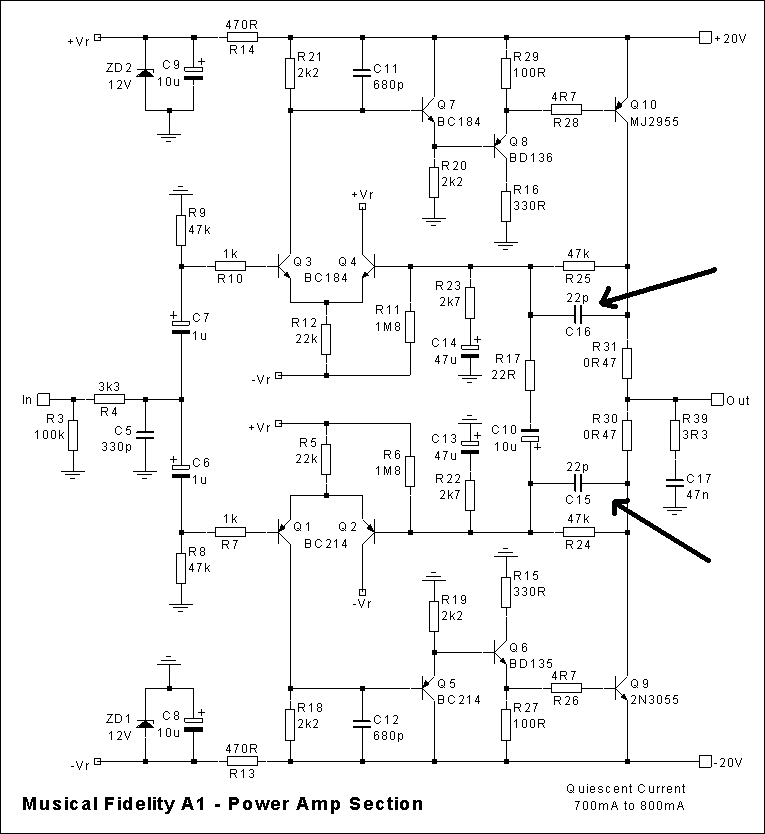
I reviewed the schematics (which are plentiful on the net - example below) and noted C15 and C16 are on the signal path.
Since I did not have the original pix of my A1X, I will use the following from the internet to illustrate the caps I am referring to e.g caps with 22 written and indicated by the arrow pointers in red.
sample with arrowed indicators
I replaced these 22pf caps with 33pf silver mica's. When tested, it sounded like a valve unit - warm, full bodied with all the details!!!

When the buyer of my (previous) A1X first heard the unit, he literally "fell head-over-heels" over it. He had previously heard other A1 and A100 units as well as the reincarnation.What more can I say ...

Tuesday, November 2, 2010

Luxman L-410

The L-410 is a Class-A bias (first few watts only) integrated amp and it really runs hot. The L410 is a high-power component, and, was previously able to drive my renown power hungry Celestion SL6S with ease.

Before re-cap, you could hear same off-key note from my Emi Fujita album (as per Nait). The offending component was traced to the pair of 'white translucent' 0.047uf non-EC cap on the pre-amp board.

After re-cap using better quality components e.g Wima, OSCON, Panasonic FC, Elna Audio, EPCOS, Siemens, Rubycon, Panasonic ECA, Elna Starget, Nichicon, AVX, silver mica and, Philips BC, the L-410 became truly transparent. Pairs well with my recapped Musical Fidelity Tubalog and Marantz CDA-94.

Please be aware of the bi-polar caps in the power amp section.

I believe the L-410 is Class-A for the first 8W or so (not documented anywhere) as once the volume dial passes just over 9 o'clock you notice it run not as hot as before and the "grunti-ness" increases - in the Luxman tradition of the L-510, etc. The other 'give-away" is the use of the "shark-fin" heatsink normally found in vintage Luxman's which run hot.

The following is a pix of an original L-410 (not mine) which was located on the net.
Original pix from internet
The following is my set after almost all the electrolytic (except the pair of 15000uf) and most of the non-EC caps were replaced.
View from front after recap
The following is the top view.
From top

The following pix are close-up(s) of the various sections, after they have been recapped.

Pre-amp board
Tone control board


Power amp board

Saturday, October 30, 2010

Sunday, October 24, 2010

Technics SB-X700 (aka "Honeycomb speaker")


I recently acquired a pair of SB-X700 speakers in good working condition (with original speaker stands). These are quite rare in the used market. Summary of details at http://www.vintagetechnics.info/loudspeakers.htm

With cover
Cover off
Bass reflex design. Side panels sound thin when softly tab on (except the back).

Sounds pretty analog. Bass was "flabby" and mid-range lack definition. Plenty of low frequency resonance as well due to thin side panels.

Has "potential" ...

The speaker rests on a metal plate at the top of the stand. The speaker can be easily shifted when on the stand. Hence I decided to try the following. Put a "sticky mat" and eight rubber pencil erasers on each of the stands. The speaker will be place on top of the stand with the mat and erasers. The idea is to create an "iso-layer" which would absorb vibrations from the speaker e.g idea from "earthquake proof-ing" procedures!!!
Next I obtain 2 small water bottles and fill them to just over half volume. You can see them place into the internal chamber of the speaker stand on the prior picture. These will act as "dampeners" - like sand bags inside speaker stands.
Water bottles from inside speaker stand

Once done, firing the amp up verifies the theory - bass was firmer and reproduction became more natural with clearity to match!!!

Actually sounds pretty decent...